


Quick Research
Generate reliable direction feasibility study reports for your R&D in just a few steps.

Technical Q&A
Discover and master advanced knowledge NOW. Basics, ideas, possibilities, all at once.

Find Solutions
As an expert in R&D theories, this can generate solutions to your technical problems instantly.

Evaluate Feasibility
Analyze your overall solution with one click, know your potential R&D risks in advance.

Monitor Landscape
Get weekly tech updates, stay abreast of the latest tech innovations and key insights.
Connecting structure
A technology for connecting structures and fixing joints, which is applied in the direction of filtration and separation, separation methods, chemical instruments and methods, etc., can solve the problems of not being as good as coarse thread, increase cost, and cannot be used, so as to achieve good anti-loosening function and improve dismantling The effect of loading speed
- Summary
- Abstract
- Description
- Claims
- Application Information
AI Technical Summary
Problems solved by technology
Method used
Image


Examples
Embodiment 1
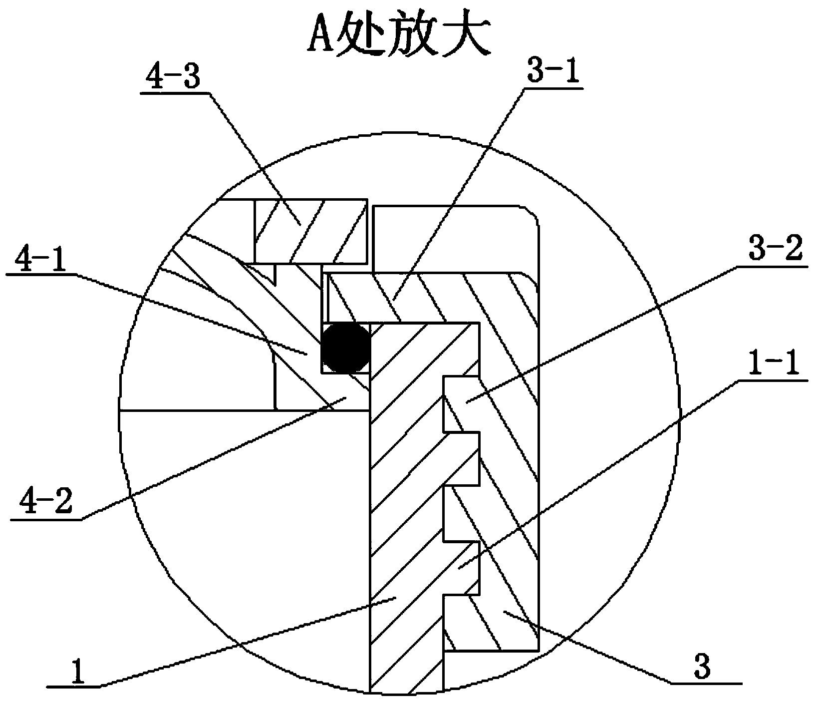
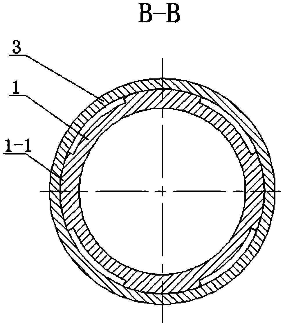
[0059] See Figure 1 to Figure 5 , The coupling structure of this embodiment includes a tubular housing 1 , a sealing ring 2 , a fixed coupling 3 and an end cap 4 .
[0060] The edge of the end cap 4 is provided with a cylindrical surface 4-1 fitted inside the tubular casing 1, and the end of the cylindrical surface 4-1 extends outwards from a first ring 4-2. The cylindrical axis of the cylindrical surface 4 - 1 is parallel to the axis of the tubular shell 1 , and the plane where the first ring 4 - 2 is located is perpendicular to the axis of the tubular shell 1 . The fixed link 3 is in the shape of a tube, and a second circular ring 3-1 extending inward toward the central axis is provided at the end thereof. The inner wall of the tubular housing 1, the inner wall of the second ring 3-1, the cylindrical surface 4-1 and the outer wall of the first ring 4-2 jointly define an annular space, and the sealing ring 2 is arranged in the annular space. The dimension of the cross sect...
Embodiment 2
[0067] See Figure 6 and Figure 7, This embodiment is basically the same as Embodiment 1, except that: the inner wall of the second ring 3-1 of the fixed coupling member 3 is provided with a first short tube 3-3. The inner wall of the tubular housing 1, the end surface of the first short pipe 3-3, the cylindrical surface 4-1 and the outer wall of the first ring 4-2 jointly define an annular space, and the sealing ring 2 is arranged in the annular space. The end cover 4 is provided with a limit cover 4-6. The limiting cover 4-6 is located outside the fixed coupling 3, and the outer diameter of the limiting ring 4-3 or the limiting cover 4-6 is larger than the inner diameter of the second ring 3-1.
Embodiment 3
[0069] See Figure 8 , This embodiment is basically the same as Embodiment 1, except that: the inner wall of the tubular casing 1 is provided with an annular platform 1-2 near the end. The inner diameter of the annular platform 1 - 2 is smaller than the outer diameter of the first circular ring 4 - 2 on the end cap 4 .
[0070] The annular platform 1-2 can stop the end cap 4 from moving inwardly from the end of the tubular casing 1. The principle of determining the position is: when assembling, when the end cap 4, the fixed coupling 3 and the tubular casing 1 are in the axial direction After the relative position reaches the set position, it can ensure that the sealing ring 2 produces enough compression. After the sealing ring 2 produces enough compression, the fixed coupling 3 or the tubular shell 1 is rotated to make the rotating fixed coupling 3 and the tubular shell The body 1 also fits in place circumferentially. The joint structure assembled in this way, the sealing ri...
PUM
 Abstract
Description
Claims
Application Information
 - R&D Engineer
- R&D Manager
- IP Professional
- Industry Leading Data Capabilities
- Powerful AI technology
- Patent DNA Extraction
Browse by: Latest US Patents, China's latest patents, Technical Efficacy Thesaurus, Application Domain, Technology Topic, Popular Technical Reports.
© 2024 PatSnap. All rights reserved.Legal|Privacy policy|Modern Slavery Act Transparency Statement|Sitemap|About US| Contact US: help@patsnap.com