
Overcurrent protection method and system for power factor correction circuit

A technology for power factor correction and current protection, applied in the field of overcurrent protection methods and systems for power factor correction circuits, can solve the problems of unstable current in the power grid, high trigger threshold, circuit damage, etc., achieve high trigger threshold, reduce overcurrent , the effect of stable operation

Active Publication Date: 2017-05-17
HANGZHOU XIANTU ELECTRONICS
View PDF4 Cites 0 Cited by
  • Summary
  • Abstract
  • Description
  • Claims
  • Application Information

AI Technical Summary

Problems solved by technology

[0008] In practice, the instability of the power grid or the influence of EMC causes the current to be too large, causing overcurrent
In the prior art, hardware is used for overcurrent protection, but when hardware overcurrent protection is used, the trigger threshold is relatively high, and the current must be large enough to trigger hardware protection.
Sometimes the overcurrent has caused damage to the circuit

Method used


Image

  • Overcurrent protection method and system for power factor correction circuit
  • Overcurrent protection method and system for power factor correction circuit
  • Overcurrent protection method and system for power factor correction circuit

Examples


Embodiment Construction

[0072] First of all, in order to enable those skilled in the art to better understand and implement the technical solution provided by the present invention, the basic composition and working principle of the following active PFC circuit will be introduced in detail below with reference to the accompanying drawings.

[0073] see figure 1 , which is a schematic circuit diagram of the active PFC provided by the present invention.

[0074] The alternating current power supply AC is rectified by the rectifier 100 to be output as a direct current. figure 1 The rectifier in is a full bridge and consists of four diode connections, namely the first diode D1, the second diode D2, the third diode D3 and the fourth diode D4.

[0075] It should be noted that the voltage at the output terminal of the rectifier 100 is direct current. It can be understood that after the alternating current power supply AC is rectified, the cycle of the direct current power source is half of the cycle of the...


PUM


Abstract

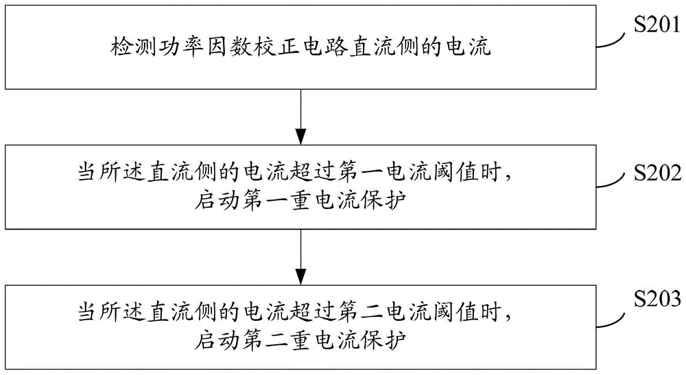
The invention provides a method and a system for over-current protection of a power factor correction circuit. The method includes that by setting of duel protections, when current on the direct-current side exceeds a first current threshold, the first current protection is applied, and when the current on the direct-current side exceeds a second current threshold, the second current protection is applied; during the first current protection, the current on the direct-current side is not too large, and when voltage of an alternating-current power supply passes zero next time, an PWM (pulse width modulation) pulse signal is restored and outputted; during the second current protection, the current on the direct-current side is larger already, the PWM pulse signal is stopped to be outputted and is outputted again till the circuit restores to the normal state, the PWM pulse signal outputted again is an adjusted new PWM pulse signal, the circuit is enabled to run normally, and the situation of overcurrent is reduced. By the method, over-current protection is realized through software and more effective than hardware protection. Probability of PFC (power factor correction) restart is lowered, and the circuit is enabled to run more stably and is protected from being damaged by overcurrent.

Description

technical field [0001] The invention relates to the technical field of power factor correction, in particular to an overcurrent protection method and system for a power factor correction circuit. Background technique [0002] With the improvement of industrial production level and people's living standard, more and more harmonics are generated in the grid by a large number of non-linear electrical equipment, which not only increases the loss of grid power supply, affects the normal operation of grid protection devices, but also The power factor of the electrical equipment is reduced. [0003] Inverter air conditioners are non-linear electrical equipment. Therefore, in order to suppress harmonic generation and improve power factor, power factor correction (PFC, Power Factor Correction) technology is introduced into inverter air conditioners. [0004] The basic idea of ​​PFC is that the input current waveform tends to be as sinusoidal as possible and the phase difference with...

Claims


Application Information

Patent Timeline
Patent Type & Authority Patents(China)
IPC IPC(8): H02M1/32H02M1/42H02H7/12H02H3/06
CPCY02B70/10
Inventor 赵鸣裘圆
Owner HANGZHOU XIANTU ELECTRONICS
Learn More