Discharging tray for rubber track

A rubber crawler and discharge tray technology, which is applied in the field of discharge trays for rubber crawlers, can solve the problems that the discharge tray cannot be adjusted, production demand cannot be adjusted, etc., and achieve reduced work intensity and danger, high practical performance, and reduced production cost effect

Active Publication Date: 2016-09-14
湖州倍格曼新材料股份有限公司
View PDF4 Cites 0 Cited by
  • Summary
  • Abstract
  • Description
  • Claims
  • Application Information

AI Technical Summary

Problems solved by technology

[0003] The technical problem to be solved by the present invention is that the existing discharge tray cannot be adjusted well and cannot be adjusted according to production requirements, which effectively increases the production cost and the work intensity brought by the replacement of the discharge tray, thereby providing a rubber crawler With discharge tray

Method used


Image

  • Discharging tray for rubber track
  • Discharging tray for rubber track
  • Discharging tray for rubber track

Examples


Embodiment 1

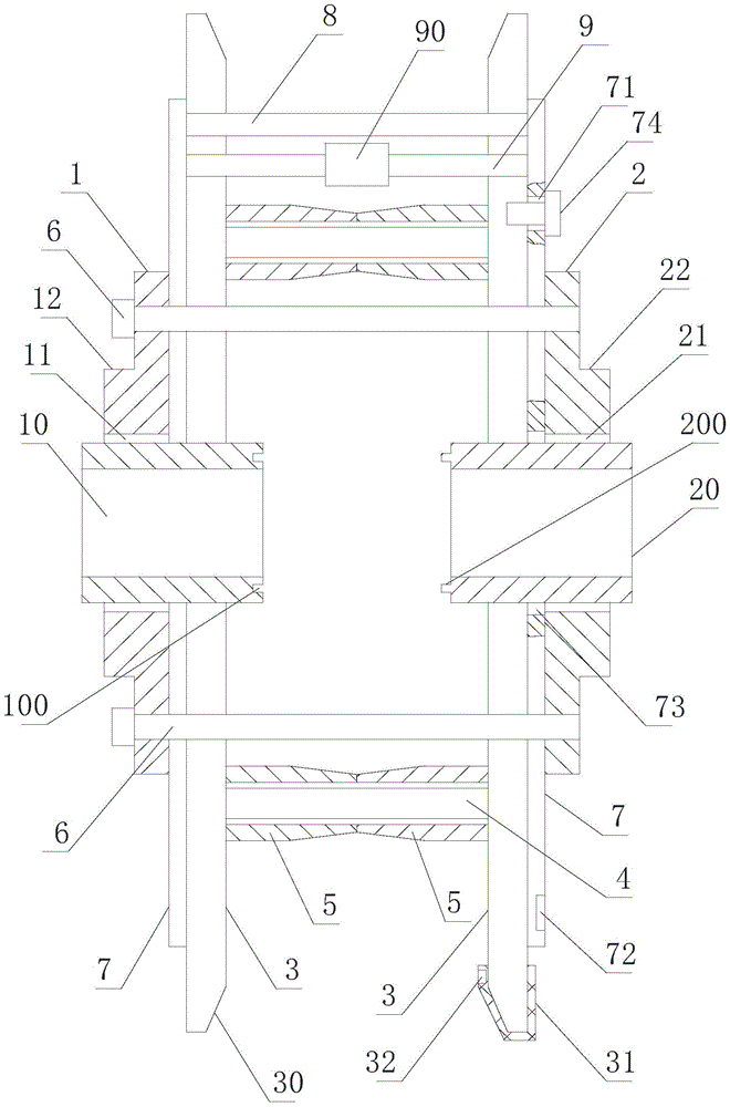
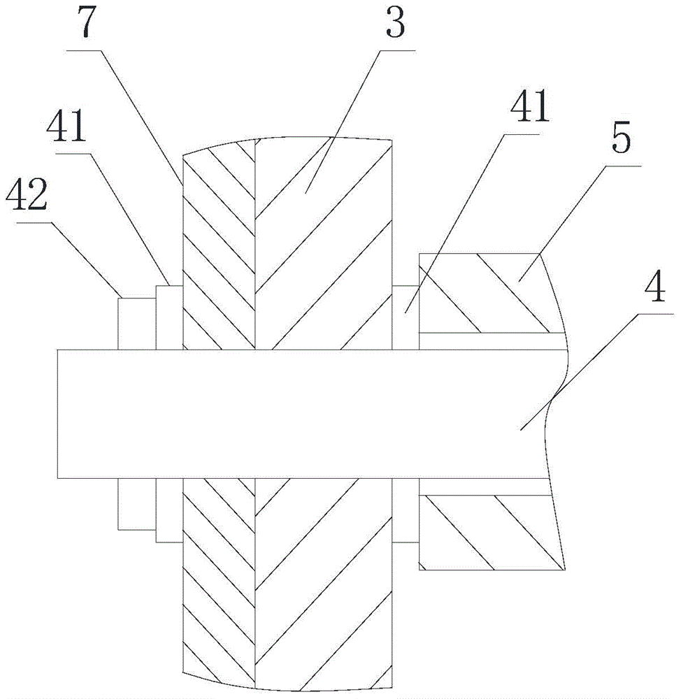
[0017] Such as figure 1 , figure 2 , image 3 As shown, a discharge tray for rubber tracks includes a left baffle 1, a right baffle 2, and several pieces are arranged between the left baffle 1 and the right baffle 2 for adjusting the left baffle 1 and the right baffle 2. The screw rod 6 of spacing between, described left baffle plate 1 and right baffle plate 2 are provided with the threaded hole that matches with screw rod 6, and the inner side wall of described left baffle plate 1 is provided with first axle sleeve 10, and described The middle part of the left baffle 1 is provided with a first installation hole 11 installed with the first bushing 10, and the first bushing 10 is penetrated in the first installation hole 11, and the inner side wall of the right baffle 2 is provided with There is a second shaft sleeve 20, and the middle part of the right baffle plate 2 is provided with a second mounting hole 21 connected with the second shaft sleeve 20, and the second shaft s...

Embodiment 2

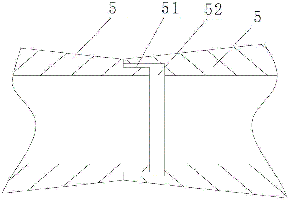
[0019] A discharge pan for a rubber track as described in Embodiment 1, this embodiment has the following differences: as Figure 4 As shown, the guide roller 5 is one, and the middle part of the guide roller 5 is provided with an inwardly arranged groove 55, the bottom end of the groove 55 is arc-shaped, and the two sides of the groove 55 Both ends are provided with a downward-sloping inclined part, which is easy to install and has a good rotation effect. The setting of the inclined part is convenient for discharging and has good practical performance.

[0020] When the unwinding tray is rewinding, adjust the distance between the left baffle 1 and the right baffle 2 through the screw 6 to adjust the receiving area, so as to rewind according to the amount of production. When rewinding, turn the unwinding tray The rubber crawler is wound along the circle formed by the guide roller 5 in sequence. When discharging, the discharge tray is fixedly connected to the discharge shaft th...


PUM


Abstract

The invention relates to a discharge pan for rubber crawlers, comprising a left baffle, a right baffle, a screw, a baffle rod, and a stopper. The left baffle is provided with a first bushing, and the right baffle is provided with a second bushing. , the baffle rods are fixedly connected by a pin shaft, and a guide roller is set on the pin shaft, and the center of the pin shaft is set on the same circle. Sleeve; the advantages of the present invention: the distance between the left baffle and the right baffle is adjusted by the screw, which can adapt to the winding problem caused by different production volumes, and reduces the work caused by the disassembly of the original winding device when it is fully loaded The strength and danger reduce the production cost caused by the original need for multiple winding devices for winding. The discharge of the rubber track is controlled by the guide roller on the pin shaft between the left baffle and the right baffle. When discharging, the rubber track can be controlled to discharge smoothly through the guide bushing and guide roller provided on the baffle, which reduces the vibration of the discharging tray during discharging.

Description

technical field [0001] The invention relates to a discharge pan for rubber crawlers. Background technique [0002] After the rubber track is produced, it needs to be rewound and placed on the discharge tray. When the existing rewinding device is rewinding the rubber crawler, the rewinding space on the rewinding device remains unchanged, which results in the rewinding of the rubber track. The limitations of the crawler belt increase the number of winding devices, thereby increasing the production cost. When the winding device is replaced and installed, there is a large workload. When the fully loaded winding device is disassembled, there is safety performance, which affects the operation. Personnel, use effect is poor, can not carry out winding according to production demand, production efficiency is low, and practical performance is low. Contents of the invention [0003] The technical problem to be solved by the present invention is that the existing discharge tray canno...

Claims


Application Information

Patent Timeline
Patent Type & Authority Patents(China)
IPC IPC(8): B65H75/24B65H75/18
Inventor 杨勇
Owner 湖州倍格曼新材料股份有限公司
Why Eureka
Try Eureka