Auxiliary handles and reciprocating work tools with auxiliary handles

A technology for assisting handles and working tools, applied in the field of reciprocating working tools, can solve problems such as the rotation limitation of the handle, and achieve the effects of improving performance and improving anti-vibration.

Active Publication Date: 2016-05-18
MAKITA CORP
View PDF7 Cites 0 Cited by
  • Summary
  • Abstract
  • Description
  • Claims
  • Application Information

AI Technical Summary

Problems solved by technology

[0005] However, in the above-mentioned anti-vibration handle, since the rotation shaft is provided inside the handle part, depending on the structure of the handle part, the rotation of the handle part may be restricted by the handle part itself.

Method used


Image

  • Auxiliary handles and reciprocating work tools with auxiliary handles
  • Auxiliary handles and reciprocating work tools with auxiliary handles
  • Auxiliary handles and reciprocating work tools with auxiliary handles

Examples


no. 1 Embodiment approach

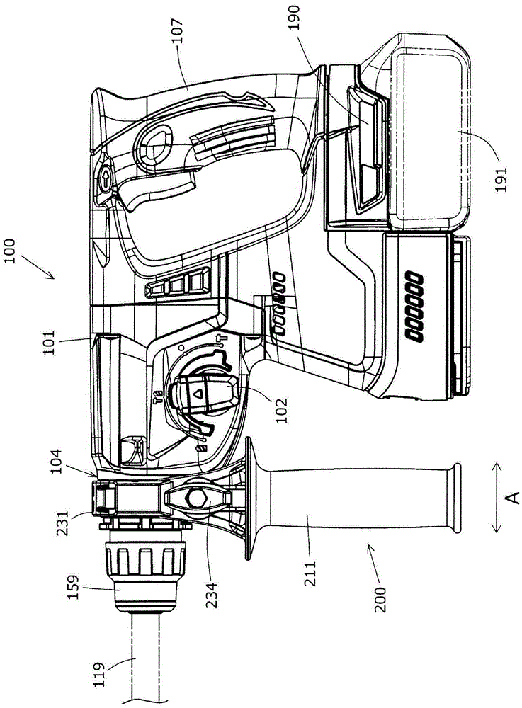
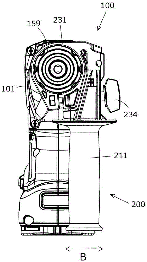
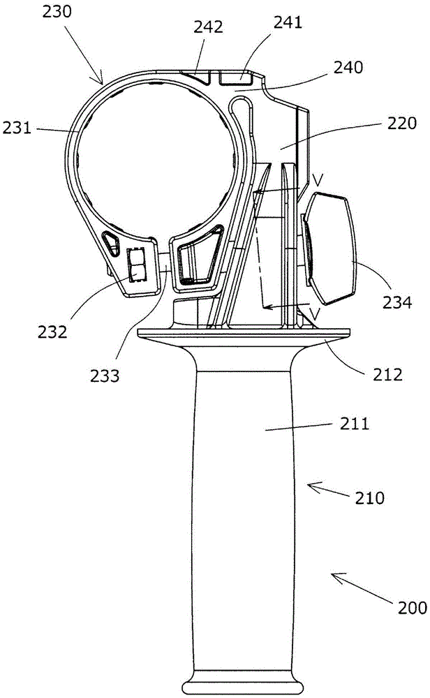
[0038] Below, refer to Figure 1 to Figure 5 Embodiments of the present invention will be described in detail. Such as figure 1 As shown, the auxiliary handle 200 is detachably attached to the hammer drill 100 . The hammer drill 100 is mainly composed of a main body 101 , a handle handle 107 , and a hammer head 119 .

[0039] Such as figure 1 As shown, the main body portion 101 has a tool holder 159 and a barrel portion 104 on its front side. The hammer head 119 is detachably attached to the tool holder 159 . On the other hand, a handle grip 107 is attached on the rear side opposite to the front side of the main body portion 101 . Also, a battery mounting portion 190 for mounting a battery pack 191 is provided below the handle handle 107 of the main body 101, and the battery pack 191 is detachable.

[0040] Inside the main body 101 are housed a motor, a power conversion mechanism that transmits the output force of the motor to the striker 119 , an impact mechanism, and a...

no. 2 Embodiment approach

[0055] Below, refer to Image 6 A second embodiment will be described. Similar to the first embodiment, the auxiliary handle 300 is detachably attached to the cylindrical portion 104 of the hammer drill 100 . The auxiliary handle 300 is mainly composed of a handle portion 310 , a handle holding portion 320 , a mounting portion 330 , and a support portion 340 .

[0056] The handle portion 310 has an elongated handle 311 and a flange portion 312 provided on the handle holding portion 320 side. The handle part 310 is an embodiment corresponding to the "grip part" of the present invention.

[0057] The mounting portion 330 is mainly composed of an annular portion 331 . Nuts 332 and bolts 333 are provided on the annular portion 331 . A knob 334 is provided on the bolt 333 . The bolt 333 is tightened by turning the knob 334 , so that the mounting part 330 is mounted on the cylinder part 104 . This mounting part 330 is an embodiment corresponding to the "mounting part" of the p...


PUM


Abstract

The present invention provides an auxiliary handle capable of effectively improving the performance of the auxiliary handle mounted on the work tool, and a reciprocating work tool with the auxiliary handle. The auxiliary handle (200) has a handle part (210), a handle holding part (220), a mounting part (230) and a supporting part (240). The handle holding part (220) is arranged in the long axis direction of the auxiliary handle (200), and is located between the handle part (210) and the support part (240). In addition, in the state where the auxiliary handle (200) is mounted on the main body of the work tool, the handle portion (210) and the handle holding portion (220) maintain a relative relationship with the mounting portion (230) with the support portion (240) as a fulcrum. move.

Description

technical field [0001] The invention relates to an auxiliary handle installed on a reciprocating working tool and a reciprocating working tool with the auxiliary handle. Background technique [0002] An anti-vibration handle mounted on a working tool is disclosed in Japanese Patent Laid-Open Publication No. 2005-081517. In this anti-vibration handle, a rotation shaft is provided on the power tool main body side inside the handle portion, and a compression spring is provided on the distal end side opposite to the power tool main body side. [0003] patent documents [0004] Patent Document 1: Japanese Invention Patent Laid-Open Publication No. 2005-081517 [0005] However, in the above-mentioned anti-vibration handle, since the rotation shaft is provided inside the handle portion, depending on the structure of the handle portion, the rotation of the handle portion is restricted by the handle portion itself. Therefore, in view of the above problems, an object of the present...

Claims


Application Information

Patent Timeline
Patent Type & Authority Patents(China)
IPC IPC(8): B25F5/02
CPCB25F5/006B25F5/026B25F5/02B25D17/043B25D17/04B25G1/01
Inventor 吉兼圣展町田吉隆
Owner MAKITA CORP
Why Eureka
Try Eureka