Eureka AIR delivers breakthrough ideas for toughest innovation challenges, trusted by R&D personnel around the world.

Device for positioning an object in space

A positioning device and target positioning technology, applied in the field of positioning devices or micro-moving positioning devices, can solve problems such as loss of dimensional stability, achieve good distribution, and solve the effect of dimensional stability problems

Active Publication Date: 2014-12-10
HORIBA ABX SAS
View PDF6 Cites 0 Cited by
  • Summary
  • Abstract
  • Description
  • Claims
  • Application Information

AI Technical Summary

Problems solved by technology

[0021] The absence of springs also partly solves the problem of dimensional stability of the whole device in case of temperature changes, since the springs cannot be made of the same material as the plate, otherwise, in case of temperature changes, damage to the Poor expansion / contraction of the dimensional stability of the whole device especially the micro-motion device

Method used


Image

  • Device for positioning an object in space
  • Device for positioning an object in space
  • Device for positioning an object in space

Examples


Embodiment Construction

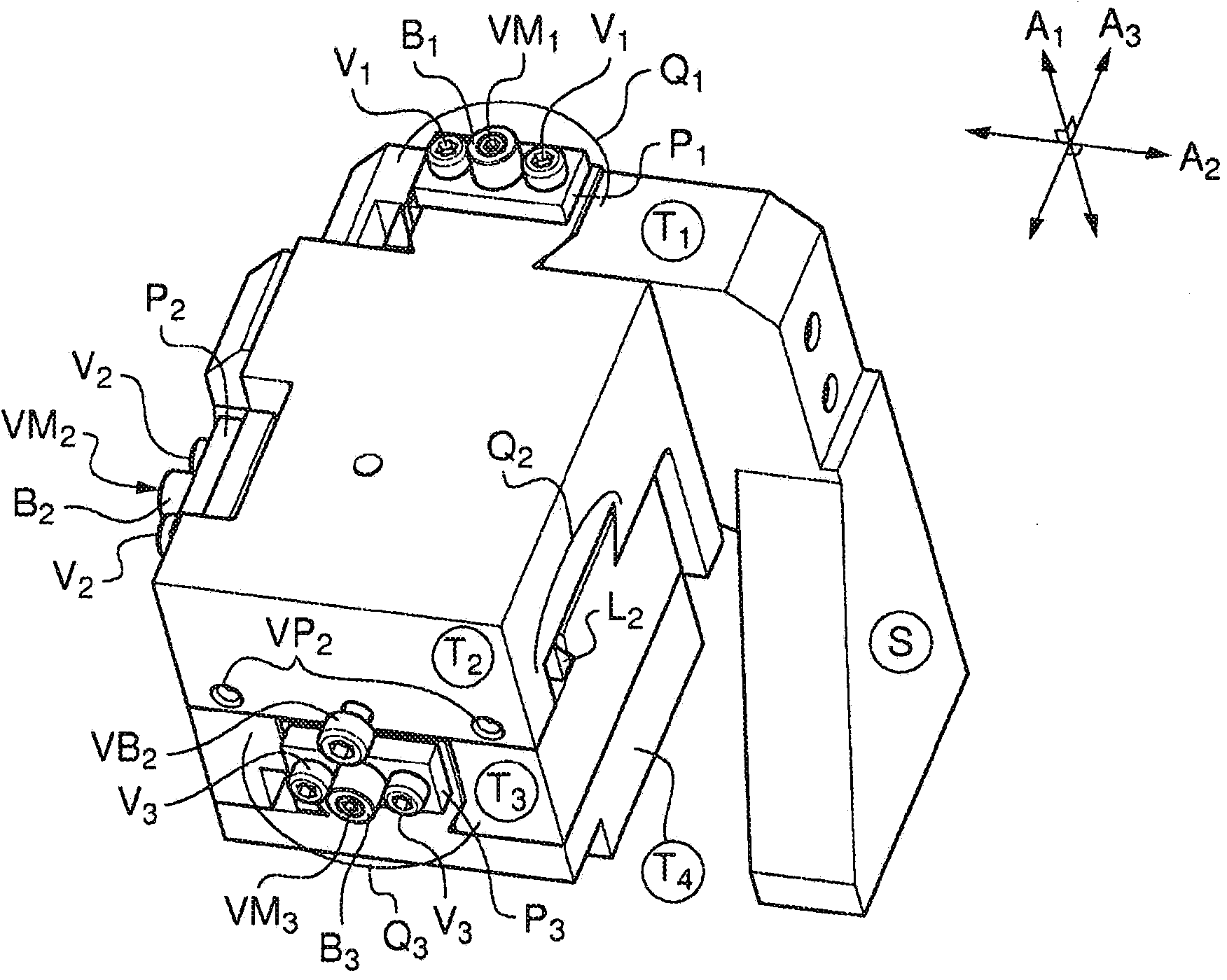
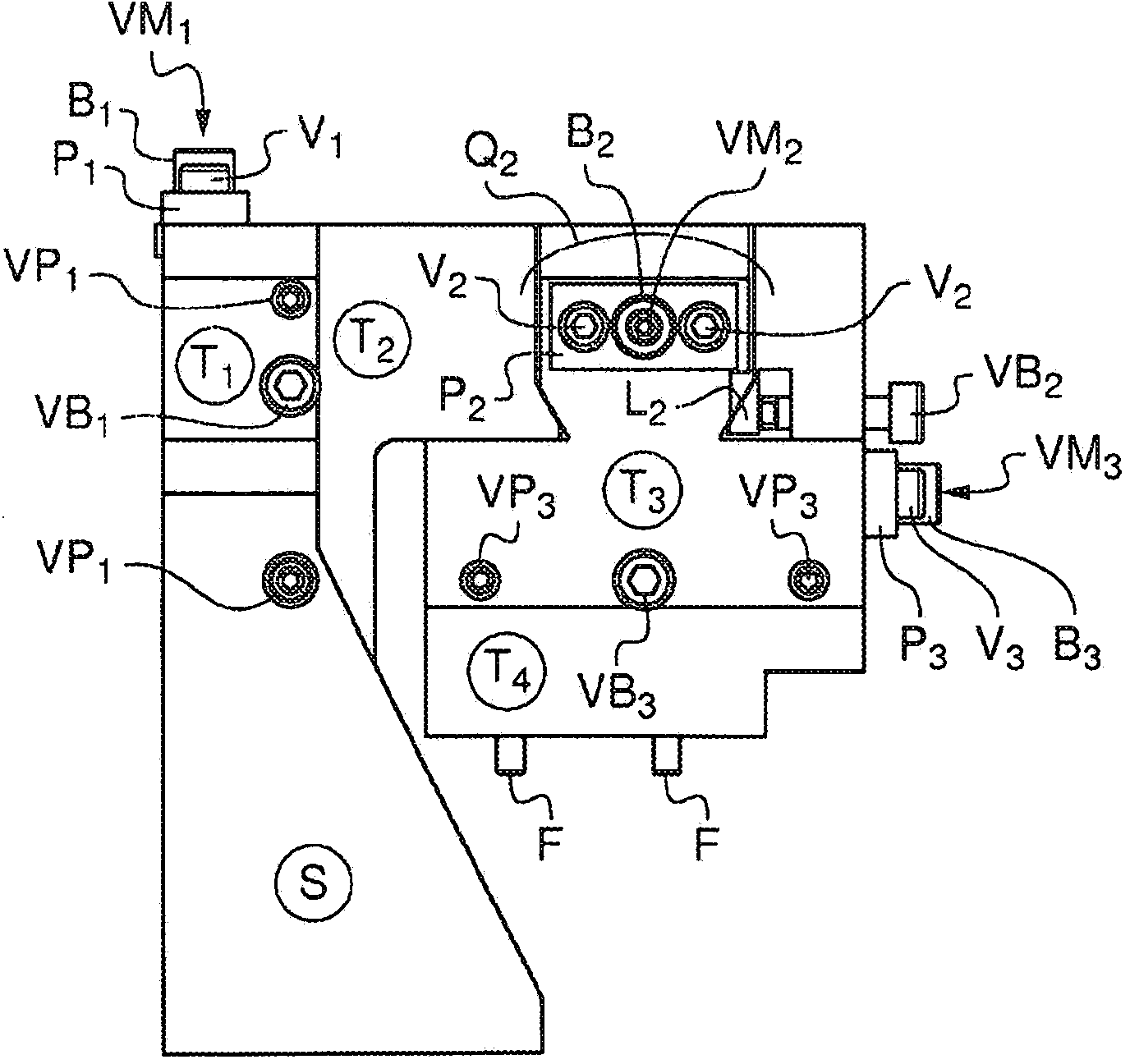
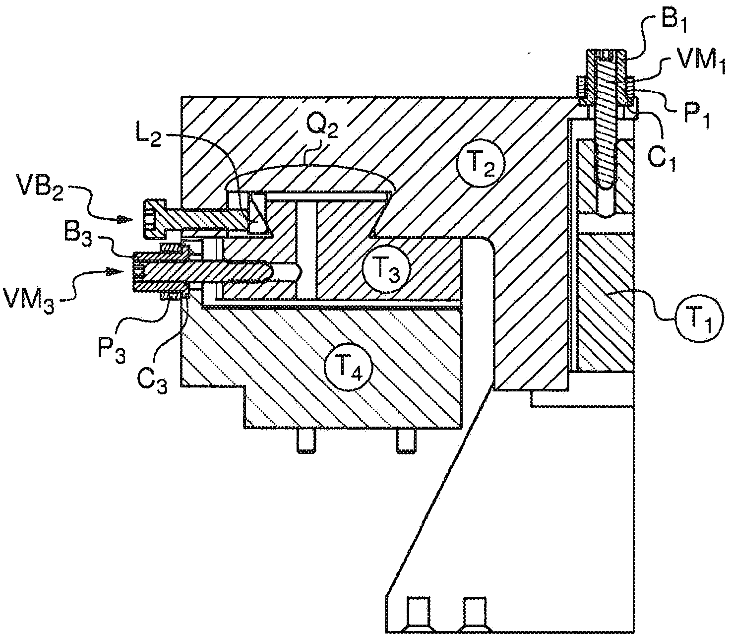
[0062] figure 1 is a three-dimensional view of an implementation variant of the device of the present invention, showing the four plates (T1, T2, T3 and T4) of the device, and the possibility to make the plates T1 and T2 (Q1), T2 and T3 (Q2) and T3 and T4 (Q3) a dovetail pin / groove system (Q) that moves relative to the other.

[0063] Note that for each pin / tongue-and-groove system there is one microscrew VM (VM1 for system Q1, VM2 for system Q2, VM3 for system Q3). Each microscrew VM is held connected to the plate with said microscrew by a ring B (B1, B2 and B3), which is itself supported by a mounting plate P (P1, P2 , P3), said mounting plate P (P1, P2, P3) itself is held by two screws V (V1 for ring B1, V2 for ring B2, V3 for ring B3).

[0064] It is to be noted that on plate T2 a locking screw (VB2) is visible which acts on the pin / tongue and groove system Q2 (the locking screws VB1 and VB3 acting on the pin / tongue and groove system Q1 and Q3 are not shown on the figure...


PUM


Abstract

"Device for positioning an object in space" Abstract The subject matter of the invention is a device for positioning an object in space comprising at least 4 plates (T1, T2, T3, T4), each capable of moving in relation to one of the other said plates with which it is contiguous along one of the 3 axes of space, the movement of a plate in relation to another plate potentially being guided by a mortise / tenon assembly in which said tenon may be rigidly connected with one of said plates and the mortise thereof may be built into the other plate, the orientation in space of each of the mortise / tenon assemblies being different from the other 2 and along one of the 3 axes of space, characterised in that: Said device is free of all return springs; At least one of the mortise / tenon assemblies may be in a dovetailed shape; A pre-tension aimed at limiting the movement of a plate with respect to another is laterally applied to one of the edges of the tenon of the mortise / tenon assembly, said pre-tension limiting but not preventing the movement of said plates with respect to one another; The movement of at least one plate with respect to another plate may be assured by means of at least one micrometric screw that can act on at least one of the 2 plates that must be moved with respect to one another, said micrometric screw potentially being rigidly connected with one of said 2 plates, said micrometric screw potentially being fastened in direct contact with said plate; The immobilisation of one plate with respect to another plate in the desired position may be assured, independently for each of the mortise / tenon assemblies, by at least one means of immobilisation.

Description

technical field [0001] The present invention relates to the field of positioning devices for positioning objects in space, and more precisely to the field of ultra-precise or micro-motion positioning devices for positioning objects in space, especially in applications such as flux micrometry The field of positioning devices used in measuring equipment. Background technique [0002] Flux micrometry is a technique that enables high-speed sequential delivery of particles, molecules or cells carried by a carrier fluid to a light excitation source, such as a light beam, advantageously a laser beam. This technique allows, inter alia, to classify and classify said particles, molecules or cells quantitatively and / or qualitatively, respectively, quantitatively and / or qualitatively, based on the analysis of optical and / or physical signals emitted by said particles, molecules or cells passing through said optical excitation source. / or counting and / or feature determination. [0003] ...

Claims


Application Information

Patent Timeline
Patent Type & Authority Applications(China)
IPC IPC(8): G01B7/00G01B11/00G01B21/00B23Q1/00G01B5/00
CPCG01B5/0004G01N15/1459G01N15/149F16M11/043G01N15/0205G01N35/085
Inventor N·埃农
Owner HORIBA ABX SAS
Why Eureka
Eureka Blog
Learn More