Electrochemical reduction device, and method for producing hydrogenated product of aromatic hydrocarbon compound or nitrogen-containing heterocyclic aromatic compound
A technology of aromatic compounds and aromatic compounds, applied in reduction electrolysis, electrolysis process, electrolysis components, etc.
- Summary
- Abstract
- Description
- Claims
- Application Information
AI Technical Summary
Problems solved by technology
Method used
Image


Examples
Embodiment approach 1
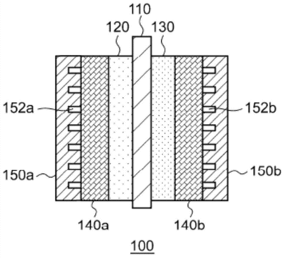
[0028] figure 1 It is a schematic diagram of the schematic structure of the electrochemical reduction apparatus 10 of embodiment. figure 2 It is a diagram showing a schematic configuration of an electrode unit included in the electrochemical reduction device 10 according to the embodiment. like figure 1 As shown, the electrochemical reduction device 10 includes an electrode unit 100 , a power control unit 20 , an organic matter storage tank 30 , a water storage tank 40 , a gas-water separator 50 , and a control unit 60 .
[0029] The power control unit 20 is, for example, a DC / DC converter that converts an output voltage of a power supply into a predetermined voltage. The positive output terminal of the power control unit 20 is connected to the positive electrode of the electrode unit 100 . The negative output terminal of the power control unit 20 is connected to the negative electrode of the electrode unit 100 . Accordingly, a predetermined voltage is applied between t...
Embodiment approach 2
[0088] Figure 5 It is a schematic diagram showing the schematic structure of the electrochemical reduction device of Embodiment 2. like Figure 5 As shown, the electrochemical reduction device 10 includes an electrode unit assembly 200 , a power control unit 20 , an organic matter storage tank 30 , a water storage tank 40 , a gas-water separation unit 50 , and a control unit 60 . The electrode unit assembly 200 has a laminated structure in which a plurality of electrode units 100 are connected in series. In this embodiment, the number N of electrode units 100 is five. In addition, the structure of each electrode unit 100 is the same as that of Embodiment 1. FIG. exist Figure 5 In the drawing, the electrode unit 100 is omitted from illustration, and the liquid diffusion layers 140a, 140b, and the separators 150a, 150 are omitted.
[0089] The positive output terminal of the power control unit 20 in this embodiment is connected to the positive terminal of the electrode un...
Embodiment approach 3
[0099] Image 6 It is a schematic diagram showing the schematic structure of the electrochemical reduction device of Embodiment 3. The basic structure of the electrochemical reduction device 10 of the present embodiment is the same as that of the second embodiment. In this embodiment, the electrode unit assembly 200 is housed in the electrolytic tank 300 . A second circulation path is provided between the electrolytic tank 300 and the water storage tank 40 , and the electrolytic tank 300 is filled with water supplied from the water storage tank 40 . The oxygen-generating electrode 130 of each electrode unit 100 is capable of flowing water filled with the electrolytic cell 300 .
[0100] The electrochemical reduction device 10 of this embodiment, in addition to the effects obtained in Embodiment 2, has the effect of increasing the in-plane temperature difference of the oxygen generating electrode 130, the temperature difference between electrode units, and The advantages of ...
PUM
| Property | Measurement | Unit |
|---|---|---|
| thickness | aaaaa | aaaaa |
| specific surface area | aaaaa | aaaaa |
| specific surface area | aaaaa | aaaaa |
Abstract
Description
Claims
Application Information
 - Generate Ideas
- Intellectual Property
- Life Sciences
- Materials
- Tech Scout
- Unparalleled Data Quality
- Higher Quality Content
- 60% Fewer Hallucinations
Browse by: Latest US Patents, China's latest patents, Technical Efficacy Thesaurus, Application Domain, Technology Topic, Popular Technical Reports.
© 2025 PatSnap. All rights reserved.Legal|Privacy policy|Modern Slavery Act Transparency Statement|Sitemap|About US| Contact US: help@patsnap.com