
A rotating server rack

A server, rotary technology, applied in the direction of rack/frame structure, support structure installation, etc., can solve the problems of messy wiring, difficult wiring and maintenance of server back-end interface, complex structure, etc., to reduce weight, facilitate wiring and maintenance , the effect of simplifying the structure

Active Publication Date: 2016-09-28
BAOJI PETROLEUM MASCH CO LTD
View PDF4 Cites 0 Cited by
  • Summary
  • Abstract
  • Description
  • Claims
  • Application Information

AI Technical Summary

Problems solved by technology

[0004] The purpose of the present invention is to provide a rotary server rack, which solves the problems of messy wiring, complex structure, difficult wiring and maintenance of the server back-end interface in the existing drawer-type server rack

Method used


Image

  • A rotating server rack
  • A rotating server rack
  • A rotating server rack

Examples


Embodiment Construction

[0019] The present invention will be described in detail below in conjunction with the accompanying drawings and specific embodiments.

[0020] The following description takes the left and right positions shown in the figure as an example, and the left and right positions can also be interchanged in actual implementation.

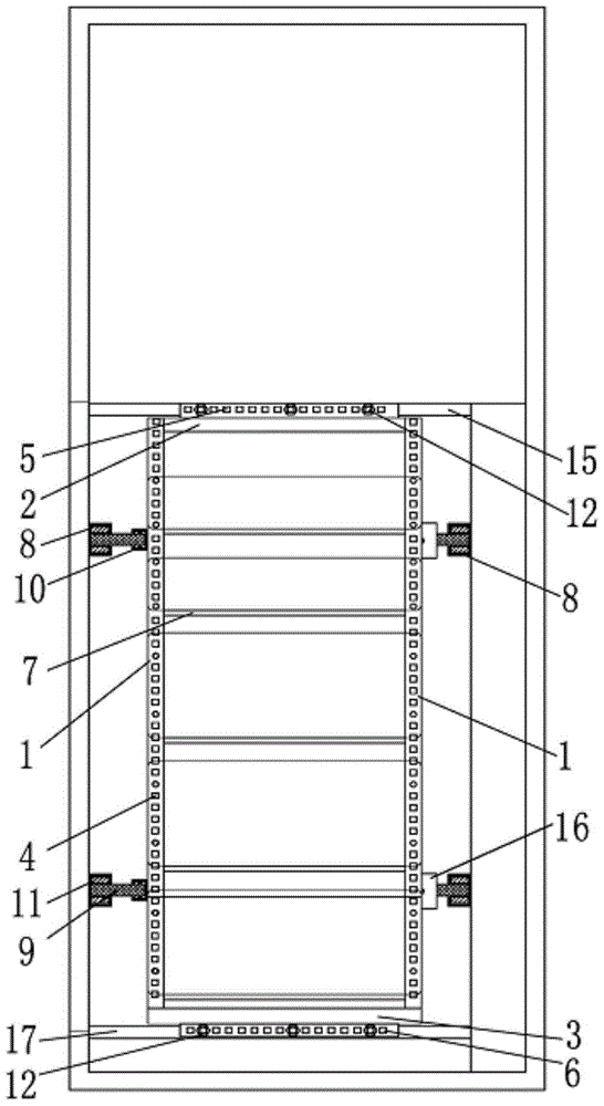
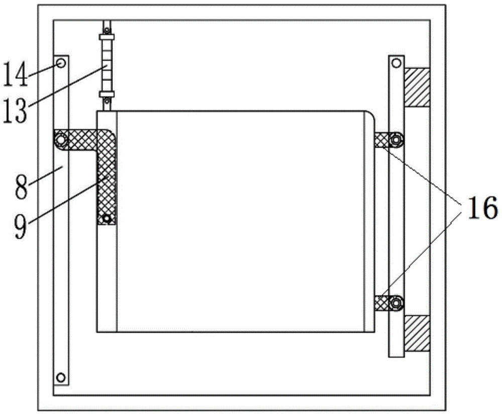
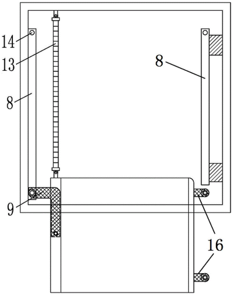
[0021] refer to figure 1 , the structure of the rotary server rack of the present invention is to include a cubic frame body (referred to as the frame for short) for installing a plurality of servers, and the cubic frame body includes four support columns 1, four upper beams 2 and four The lower beam 3 is fixedly connected, and a plurality of fixed bottom plates 7 are horizontally installed between the four support columns 1;

[0022] An upper fixed beam 15 and a lower fixed beam 17 are arranged in the server control cabinet. The upper fixed hole 5 in the upper beam 2 is fixedly connected with the upper fixed beam 15 through a set of locking bolts 12. The ...


PUM


Abstract

The invention discloses a rotary server rack, which comprises four support columns, four upper beams and four lower beams fixedly connected to form a cube frame; the server control cabinet is provided with upper and lower fixed beams, and the upper beam It is fixedly connected with the upper fixed beam, and the lower beam is fixedly connected with the lower fixed beam; a set of slide rails are installed on the upper and lower positions of the inner walls on both sides of the server control cabinet, and the upper and lower rails on the left side are slidingly installed with L-shaped left supports The left support frame is fixedly connected with the two support columns on the left side through the side fixed support; the right support frame is fixedly installed on the upper and lower positions of the two support columns on the right side, and each right support frame The other end is sleeved in the slide rail on the right side through a sliding bearing. The device of the invention has simplified structure, reduced weight, and is very convenient for wiring and maintenance.

Description

technical field [0001] The invention belongs to the technical field of oil drilling rig communication control, and relates to a rotary server rack. Background technique [0002] In the offshore platform control system, a large number of servers are used, and the servers must be installed in relatively small control cabinets. For this reason, the current main installation method is to install multiple servers into so-called drawer modules for maintenance and replacement. Sometimes the server needs to be pulled out, but the interface at the back is still not well exposed to the outside, which is inconvenient for debugging and maintenance, and the back of the cabinet is usually fixed against the wall, etc., and the window cannot be opened for maintenance and inspection at the back, so it will cause unnecessary It is troublesome, and at the same time, in order to avoid interference due to insufficient cable length when the server is pulled out, sufficient cable length should be ...

Claims


Application Information

Patent Timeline
Patent Type & Authority Patents(China)
IPC IPC(8): H05K7/18H05K7/14
Inventor 张鹏飞于兴军梁春平董兴华张媛媛
Owner BAOJI PETROLEUM MASCH CO LTD
Learn More