
Testing device for long term voltage induction and partial discharge measurement test

A technology of induced voltage and test device, applied in the direction of testing dielectric strength, etc., can solve the problems of increasing compensation amount, overvoltage, bulky and so on

Inactive Publication Date: 2014-12-10
EXAMING & EXPERIMENTAL CENT OF ULTRAHIGH VOLTAGE POWER TRANSMISSION COMPANY CHINA SOUTHEN POWER GRID
View PDF10 Cites 8 Cited by
  • Summary
  • Abstract
  • Description
  • Claims
  • Application Information

AI Technical Summary

Problems solved by technology

However, the operation conditions of the substation transformers in each substation are not the same. Some are running alone and one is in standby state; It takes a lot of time to coordinate the change of the protection setting value and go through the transaction procedures, which will affect the entire test cycle
[0004] (2) The use of intermediate frequency generators requires a more accurate calculation of the reactive power compensation capacity of the test circuit in advance; the reason: the intermediate frequency generator will self-excite due to insufficient reactive power compensation of the test circuit, and the generator will automatically Step-up, the voltage cannot be controlled to cause overvoltage, which poses a great threat to the safety of the transformer under test
Not suitable for working with capacitive loads (need to increase the amount of compensation)
[0005] (3) The whole set of equipment is heavy and bulky, and generally requires two vehicles to be transported to the field test
and very noisy
The intermediate frequency unit can only carry out the transformer induction withstand voltage and partial discharge test, and cannot do the withstand voltage and partial discharge test of other electrical equipment.

Method used


Image

  • Testing device for long term voltage induction and partial discharge measurement test
  • Testing device for long term voltage induction and partial discharge measurement test
  • Testing device for long term voltage induction and partial discharge measurement test

Examples


Embodiment Construction

[0019] The present invention provides a test device for long-term induced voltage and partial discharge measurement tests. In order to make the purpose, technical solution and advantages of the present invention clearer and clearer, the present invention will be further described in detail below with reference to the accompanying drawings and examples. It should be understood that the specific embodiments described here are only used to explain the present invention, not to limit the present invention.

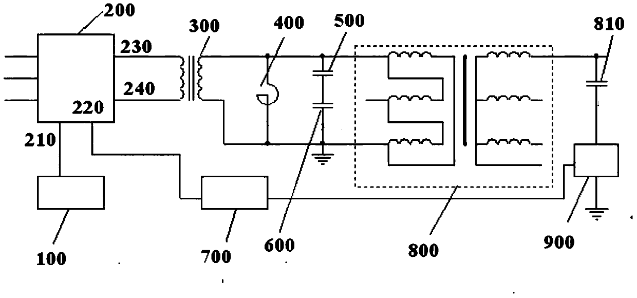
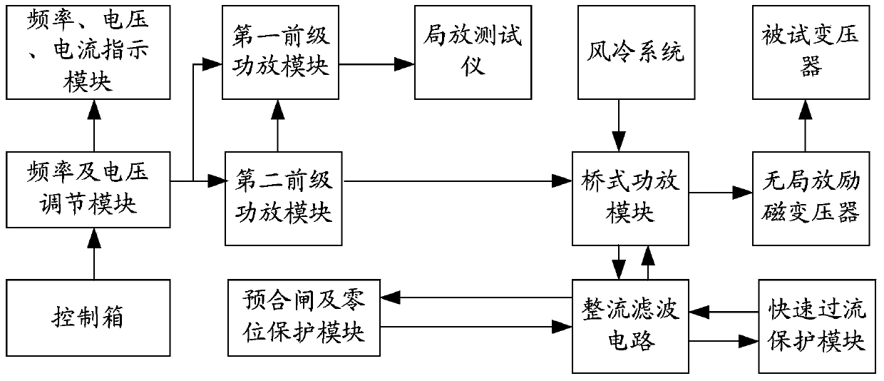
[0020] see figure 1 , figure 1 The schematic diagram of the testing device for the long-time induced voltage and partial discharge measurement test provided by the present invention, as figure 1 As shown, the test device for long-term induced voltage and partial discharge measurement test includes: control box 100, no partial discharge variable frequency power supply 200 (indicated by variable frequency power supply in the figure), no partial discharge excitation transformer ...


PUM


Abstract

The invention discloses a testing device for long term voltage induction and a partial discharge measurement test. The testing device for the long term voltage induction and the partial discharge measurement test uses a sine wave non-partial-discharge power source cooperatively with a non-partial-discharge exciting transformer, a non-partial-discharge compensation reactor, a non-partial-discharge voltage divider and other non-partial-discharge measurement devices, and completes the test according to a parallel resonance principle. Accordingly, in a parallel circuit composed of a non-partial-discharge variable frequency power source, a tested transformer equivalent capacitor and the non-partial-discharge compensation reactor, capacitive reactive power of a tested transformer is exactly equal to inductive reactive power of the non-partial-discharge compensation reactor, energy can be exchanged between the tested transformer equivalent capacitor and the non-partial-discharge compensation reactor, and the non-partial-discharge variable frequency power source does not need to provide reactive power to the non-partial-discharge exciting transformer and the non-partial-discharge compensation reactor, and only needs to provide resistive loss of a whole test circuit.

Description

technical field [0001] The invention relates to the technical fields of high-voltage technology and on-site transfer test of transformers, in particular to a test device for long-term induced voltage and partial discharge test. Background technique [0002] At present, the on-site test system for partial discharge of transformers is mainly divided into intermediate frequency generator power system and frequency conversion tuning power system. Before the popularization of frequency conversion tuning power supply, the medium frequency generator set was generally used as the test power supply in the field, and the test was carried out with a proper compensation method, and its advantages and disadvantages were more prominent. Some of the difficulties encountered when using the medium frequency generator set for the test are mainly as follows: [0003] (1) The starting current of the intermediate frequency generator is very large, usually reaching about 1000A, and its power sup...

Claims


Application Information

Patent Timeline
IPC IPC(8): G01R31/12
Inventor 伍衡宋作森夏谷林楚金伟杨方明周海滨梁晨张良刘青松张新波
Owner EXAMING & EXPERIMENTAL CENT OF ULTRAHIGH VOLTAGE POWER TRANSMISSION COMPANY CHINA SOUTHEN POWER GRID
Learn More