
Device and method for measuring slippage among gas phase, liquid phase and solid phase in shaft annulus

A wellbore annulus and measurement method technology, applied in the field of oil and gas wells, can solve the problems of lack of measurement equipment and methods

Inactive Publication Date: 2014-12-10
CHINA UNIV OF PETROLEUM (BEIJING)
View PDF9 Cites 17 Cited by
  • Summary
  • Abstract
  • Description
  • Claims
  • Application Information

AI Technical Summary

Problems solved by technology

[0006] The purpose of the present invention is to solve the above-mentioned deficiencies, and to provide a slip measurement device and method for the gas-liquid-solid three-phase slippage in the wellbore annulus, so as to solve the problem in the prior art that there is no measurement device and method for the gas-liquid-solid three-phase slippage in the wellbore annulus

Method used


Image

  • Device and method for measuring slippage among gas phase, liquid phase and solid phase in shaft annulus
  • Device and method for measuring slippage among gas phase, liquid phase and solid phase in shaft annulus
  • Device and method for measuring slippage among gas phase, liquid phase and solid phase in shaft annulus

Examples


Embodiment Construction

[0044] The above solution will be further described below in conjunction with specific embodiments. It should be understood that these examples are used to illustrate the present invention and not to limit the scope of the present invention. The implementation conditions adopted in the examples can be further adjusted according to the conditions of specific manufacturers, and the implementation conditions not indicated are usually the conditions in routine tests.

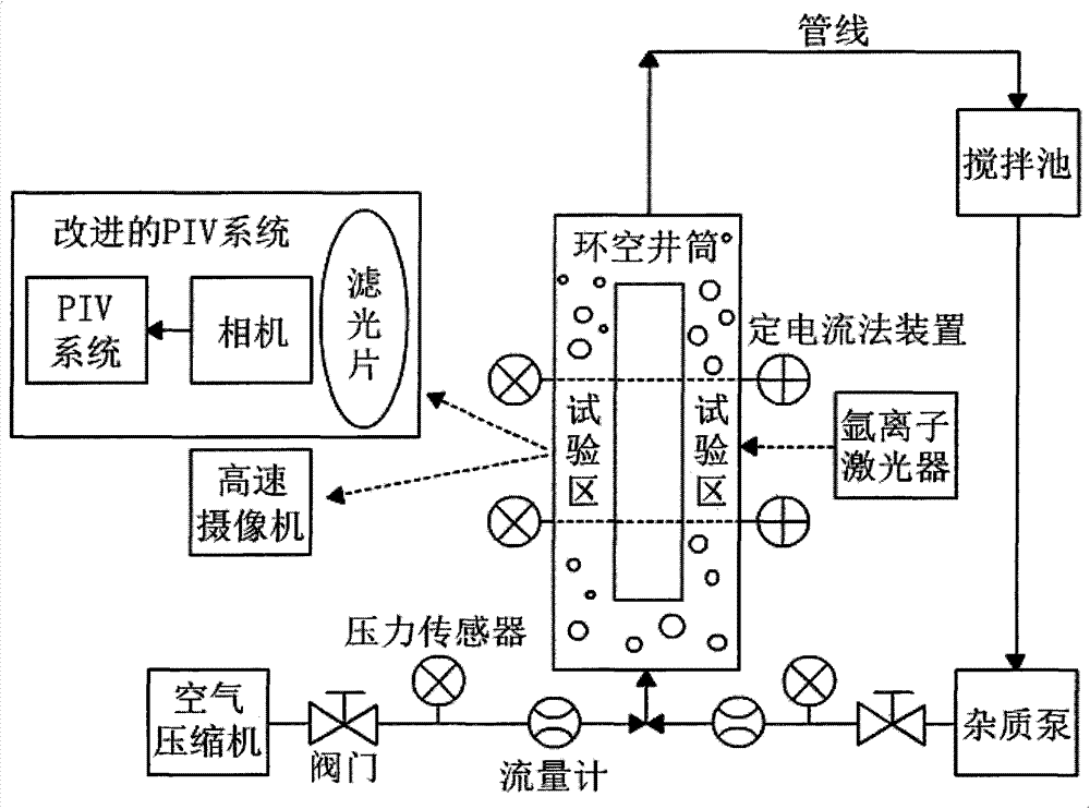
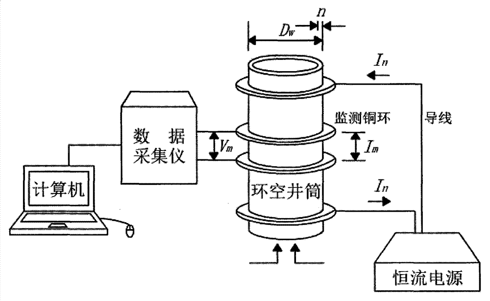
[0045] Please refer to Figure 1 to Figure 2 , figure 1 Schematic diagram of the layout of the gas-liquid-solid three-phase slip measurement equipment in the wellbore annulus provided by the embodiment of the present invention; figure 2 It is a schematic diagram of the structure of the device for measuring the cross-sectional gas fraction by the constant current method provided by the embodiment of the present invention.

[0046] In a specific embodiment, a device for measuring slippage between gas-liquid-solid ...


PUM

PropertyMeasurementUnit
Diameteraaaaaaaaaa

Abstract

The invention provides a device and method for measuring slippage among a gas phase, a liquid phase and a solid phase in a shaft annulus. The device is composed of an annulus shaft, an improved PIV system, a constant-current method device, a high-speed camera, a stirring pool, an impurity pump, an air compressor, a pressure sensor, a flow meter, a pipeline and a valve. The PIV system, the laser induction technology, the refraction index matching technology, the constant-current method and the high-speed camera recording technology are combined for the first time, and the slippage characteristics in flowing of the air phase, the liquid phase and the solid phase in the shaft annulus are systemically studied through transparent drilling fluid and transparent rock debris. According to the device and the method, the specific expressions of the laws and the slippage speeds of slipping modes when debris and gas flow in the gas phase, the liquid phase and the solid phase in the shaft annulus are obtained through tests for studying the stickness of different types of drilling fluid, drilling fluid flow, debris concentration and the section air voids factors, and effective technology support is provided for process design and well control safety of well drilling.

Description

technical field [0001] The invention relates to a detection technology in the field of oil and gas wells, in particular to a device and method for measuring the slippage between gas-liquid-solid three-phase in the annular space of a wellbore. Background technique [0002] The three-phase flow of cuttings, gas and drilling fluid generally exists in the wellbore annulus during drilling. The slippage mode and slippage speed between the three-phase mobile phases directly determine the flow state of the three-phase flow and the pressure distribution of the wellbore. Due to the gas-liquid-solid three-phase flow There are huge differences in properties between phases, frequent changes in flow patterns between phases, mutual shielding between phases, and difficulty in identifying solid particles and gases. Most of the research on gas-liquid-solid three-phase flow focuses on the macroscopic pressure distribution, while it is difficult to study the microscopic interphase slippage chara...

Claims


Application Information

Patent Timeline
IPC IPC(8): E21B47/00
Inventor 杨晨黄中伟史怀忠宋先知
Owner CHINA UNIV OF PETROLEUM (BEIJING)
Learn More