
Mouse-driven-rotating-cage-imitated spherical robot

A spherical robot and mouse technology, applied in the fields of motor vehicles, transportation and packaging, etc., can solve the problems of unfavorable industrial production of spherical robots, high cost, complicated drive control, etc., and achieve simple and feasible drive mode, low production cost and simple structure Effect

Inactive Publication Date: 2014-12-10
UNIV OF ELECTRONICS SCI & TECH OF CHINA
View PDF11 Cites 2 Cited by
  • Summary
  • Abstract
  • Description
  • Claims
  • Application Information

AI Technical Summary

Problems solved by technology

[0009] However, the existing spherical robots have complex structures, complex drive control, and high cost, which is not conducive to the industrial production of spherical robots, and it is difficult to realize the popularization and application of spherical robots

Method used


Image

  • Mouse-driven-rotating-cage-imitated spherical robot
  • Mouse-driven-rotating-cage-imitated spherical robot
  • Mouse-driven-rotating-cage-imitated spherical robot

Examples


Embodiment Construction

[0027] The present invention will be further elaborated below in conjunction with the accompanying drawings.

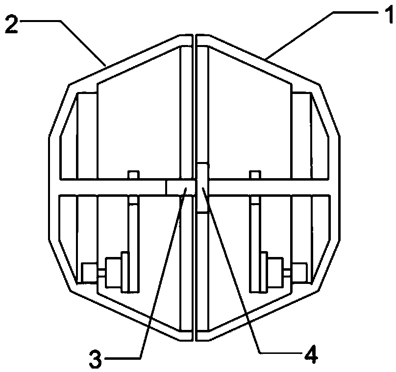
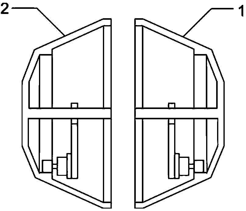
[0028] Such as figure 1 As shown, a spherical robot imitating a mouse-driven cage includes a right hemispherical shell 1, a left hemispherical shell 2, a connector 3 and a bearing 4, the outer ring of the bearing 4 is fixedly connected with the right hemispherical shell 1, and the inner ring of the bearing 4 The ring is fixedly connected with the left hemispherical shell 2 through the connecting piece 3 . The right hemispherical shell 1 and the left hemispherical shell 2 are combined into a spherical robot through the connecting piece 3 and the bearing 4, and through the bearing 4, the right hemispherical shell 1 and the left hemispherical shell 2 can cooperate to realize fast and slow combined motion so that the spherical robot can advance, retreat, turn and braking etc.

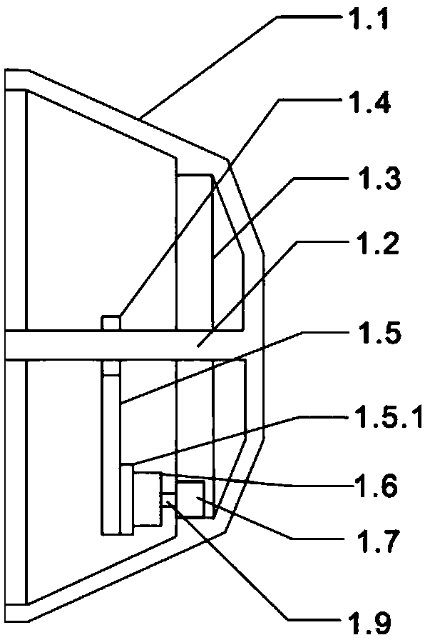
[0029] Such as image 3 As shown, the right hemispherical shell 1 includes a spherical crown...


PUM


Abstract

The invention discloses a mouse-driven-rotating-cage-imitated spherical robot which specifically comprises a right hemisphere shell (1), a left hemisphere shell (2), a connecting piece (3) and a bearing (4). The outer ring of the bearing (4) is fixedly connected with the right hemisphere shell (1), and the inner ring of the bearing (4) is fixedly connected with the left hemisphere shell (2) through the connecting piece (3). The right hemisphere shell (1) and the left hemisphere shell (2) are combined through the connecting piece (3) and the bearing (4) to form the spherical robot, and the right hemisphere shell (1) and the left hemisphere shell (2) can be matched to achieve fast-slow combined movement through the bearing (4) to enable the spherical robot to move forwards and backwards, make a turn, be braked and the like. The spherical robot has the advantages that the spherical robot is simple in structure, easy to carry and low in manufacturing cost, the driving mode of the spherical robot is simple and practicable, industrial production of the spherical robot can be achieved, and the spherical robot is of positive significance in exploration, application and popularization of the spherical robot.

Description

technical field [0001] The invention relates to a spherical robot, which is a new type of spherical robot designed on the principle of imitating a mouse to drive a cage. Background technique [0002] Spherical robot or spherical structure refers to a general term for a system that installs motion actuators, sensors, and controllers in a spherical shell. This type of robot has good dynamic and static balance, and can be applied in fields such as modern entertainment, home service, mechanical innovation competition, scientific exploration and military use. [0003] China Invention Patent Application No. 200910108660.0, a ball-shaped jumping robot discloses the patent of a ball-shaped robot applied by Li Bing. In addition to the motor and eccentric block that enable the robot to roll freely on the ground, it also has a set that can jump when encountering obstacles. drive unit. [0004] China Invention Patent Application No. 201110060529.9, a spherical robot driven by double e...

Claims


Application Information

Patent Timeline
Patent Type & Authority Applications(China)
IPC IPC(8): B62D57/02
Inventor 代小林林祖雷周永春马高远梁顺林
Owner UNIV OF ELECTRONICS SCI & TECH OF CHINA
Learn More