
An assembly process of motor code disc

An assembly process and motor coding technology, which is applied in the direction of electromechanical devices, manufacturing motor generators, electrical components, etc., can solve the problems of affecting the matching accuracy of the hole shaft, damaging the photoelectric encoder, and low accuracy of the encoding disc, so as to simplify manufacturing and maintenance Difficulty, achieving low-cost production, and the effect of easy installation

Inactive Publication Date: 2016-08-17
DONGFANG ELECTRIC CORPLESHAN NEW ENERGY EQUIP
View PDF6 Cites 0 Cited by
  • Summary
  • Abstract
  • Description
  • Claims
  • Application Information

AI Technical Summary

Problems solved by technology

The installation of traditional automobile motor speed signal acquisition components adopts the split hole-shaft matching method, and the interference fit between the small shaft and the main shaft hole is used to provide the synchronous rotation power of the rotating parts of the signal device. Its structure requires high machining accuracy of the hole shaft, and the motor The shaft can easily affect the matching accuracy of the hole and shaft during the heat treatment process
[0003] Chinese patent ZL201210419202.0 discloses a photoelectric encoder that is easy to install. It includes a housing and a base. The base is rotatably connected to a blind hole shaft. The blind hole shaft is threaded to the motor shaft. Together with the photoelectric conversion module and printed circuit board inside the casing, it is used as a speed signal generator to transmit the motor speed signal to the outside, but the structure is connected by a segmented shaft thread, and the rotation accuracy of the rotating code disc is not high, and the accuracy of the code disc itself is biased. Low, difficult to adapt to high-precision control requirements
Chinese patent ZL201020685432.8 discloses a self-adaptive support installation device for photoelectric encoders, which has a certain self-adaptive ability and can solve the problem of damage to the photoelectric encoder due to large serial movement of the motor rotor in the axial direction during operation to a certain extent. However, the stability and reliability of the articulated arm need to be tested

Method used


Image

  • An assembly process of motor code disc
  • An assembly process of motor code disc

Examples


Embodiment Construction

[0014] The present invention will be further described below in conjunction with accompanying drawing, protection scope of the present invention is not limited to the following:

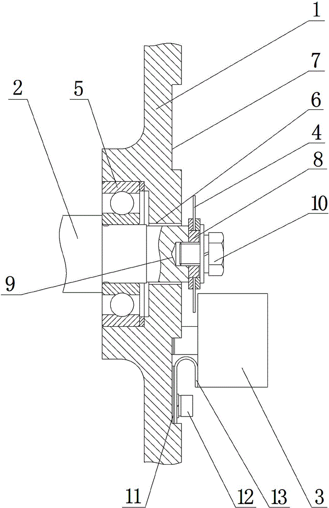
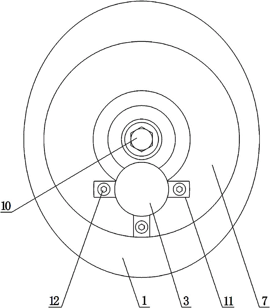
[0015] Such as figure 1 and figure 2 As shown, a motor encoder disk assembly process, which includes the following steps:

[0016] S1. First install the bearing 5 on the journal of the motor shaft 2, then pass the motor shaft 2 through the through hole 6, then install the bearing 5 in the bearing installation hole of the motor end cover 1 and fix the motor end cover 1 on the motor frame;

[0017] S2. To fix the grating disc, first set the grating disc 4 on the positioning shaft 8, and then tighten the locking bolt 10 to connect with the threaded hole 9. The locking bolt 10 limits the axial and radial movement of the grating disc 4, thereby realizing Fixed the grating disc 4;

[0018] S3, the fixing of photoelectric generator, first one side of three U-shaped adjusting gaskets 13 is all fixed on ...


PUM


Abstract

The invention discloses an assembly process of a motor encoding disc, which comprises the following steps: S1, installing a bearing (5) in a bearing installation hole of a motor end cover (1) and fixing the motor end cover (1) on a motor base Above; S2, fixing the grating disk; S3, fixing the photoelectric generator; S4, debugging after assembly, adjusting the U-shaped adjusting gasket (13) to adjust the horizontal distance between the grating disk (4) and the photoelectric generator (3) , to complete assembly debugging. The invention has the beneficial effects of simple assembly process, low-cost production of batch products, fixed assembly procedure and simple assembly, low maintenance cost, and easy adjustment of the positional accuracy of the grating disk and the light spot generator.

Description

technical field [0001] The invention relates to the technical field of assembling a motor coding disc for a vehicle, in particular to an assembling process of a motor coding disc. Background technique [0002] At present, traditional automotive motors use magnetoelectric encoders and resolvers as motor speed information acquisition components. Although magnetoelectric encoders have fewer installation structure specifications, their signal accuracy is lower; resolver signal accuracy is lower, and installation structure specifications There are many, corresponding to the number of poles of the motor, resolvers of different specifications must be selected. The use of photoelectric encoders can meet the needs of automotive drive motors with high precision in both hardware manufacturing and software processing. The installation of traditional automobile motor speed signal acquisition components adopts the split hole-shaft matching method, and the interference fit between the sma...

Claims


Application Information

Patent Timeline
Patent Type & Authority Patents(China)
IPC IPC(8): H02K15/00
Inventor 邓鸿鸣陈玉陶浩孙应龙
Owner DONGFANG ELECTRIC CORPLESHAN NEW ENERGY EQUIP
Learn More