Sweeping wind on-line foreign matter removal device and debug method for overhead power transmission line
An overhead transmission line and foreign object removal technology, applied in the direction of overhead lines/cable equipment, etc., can solve the problems of inability to clean cables, cutting the cable sheath by flying teeth, and inability to ensure the smooth removal of foreign objects, and achieve the effect of stable operation.
- Summary
- Abstract
- Description
- Claims
- Application Information
AI Technical Summary
Problems solved by technology
Method used
Image
Examples
Embodiment 1
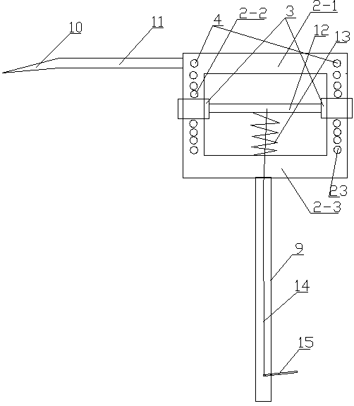
[0029] Embodiment 1: as figure 1 , 2 As shown in . The vertical rod 2-2 of the rectangular frame 2 is covered with a sliding sleeve 3 with a compression bolt 1, and the sliding sleeve 3 is provided with a lower rotating shaft 5 with a compression roller 6, and the sliding sleeve 3 is connected through a The rod 12 is fixedly connected, one end of the roller 7 is a tapered structure 8, and one end of the upper cross bar 2-1 is provided with an extension rod 11, and the free end of the extension rod 11 is provided with a blade 10 parallel to the roller 7, and the blade 10 The blade is 0.05~0.2mm from the lower horizontal plane of the roller 7, and the lower crossbar 2-3 of the rectangular frame is provided with a telescopic insulating rod 9.
[0030] The debugging method of the above-mentioned Fengwu online foreign matter removal device for overhead transmission lines includes the following steps:
[0031] 1) Observe the model of the wire and check the diameter of the wir...
Embodiment 2
[0038] Embodiment 2: as figure 1 , 2 As shown in . The vertical rod 2-2 of the rectangular frame 2 is covered with a sliding sleeve 3 with a compression bolt 1, and the sliding sleeve 3 is provided with a lower rotating shaft 5 with a compression roller 6, and the sliding sleeve 3 is connected through a The rod 12 is fixedly connected, one end of the roller 7 is a tapered structure 8, and one end of the upper cross bar 2-1 is provided with an extension rod 11, and the free end of the extension rod 11 is provided with a blade 10 parallel to the roller 7, and the blade 10 The blade is 0.05~0.2mm from the lower horizontal plane of the roller 7, and the lower crossbar 2-3 of the rectangular frame is provided with a telescopic insulating rod 9.
[0039] The above-mentioned device also includes an automatic roller compression adjustment mechanism, which includes a plurality of positioning holes 23 arranged on the vertical bar, pins arranged in the positioning holes 23, the center ...
Embodiment 3
[0049] Embodiment 3: as figure 1 , 2 As shown in . The vertical rod 2-2 of the rectangular frame 2 is covered with a sliding sleeve 3 with a compression bolt 1, and the sliding sleeve 3 is provided with a lower rotating shaft 5 with a compression roller 6, and the sliding sleeve 3 is connected through a The rod 12 is fixedly connected, one end of the roller 7 is a tapered structure 8, and one end of the upper cross bar 2-1 is provided with an extension rod 11, and the free end of the extension rod 11 is provided with a blade 10 parallel to the roller 7, and the blade 10 The blade is 0.05~0.2mm from the lower horizontal plane of the roller 7, and the lower crossbar 2-3 of the rectangular frame is provided with a telescopic insulating rod 9.
[0050] The vertical bar 2-2 is provided with scale marks.
[0051] The above-mentioned device also includes an automatic roller compression adjustment mechanism, which includes a plurality of positioning holes 23 arranged on the vertica...
PUM
 Abstract
Description
Claims
Application Information
 - R&D
- Intellectual Property
- Life Sciences
- Materials
- Tech Scout
- Unparalleled Data Quality
- Higher Quality Content
- 60% Fewer Hallucinations
Browse by: Latest US Patents, China's latest patents, Technical Efficacy Thesaurus, Application Domain, Technology Topic, Popular Technical Reports.
© 2025 PatSnap. All rights reserved.Legal|Privacy policy|Modern Slavery Act Transparency Statement|Sitemap|About US| Contact US: help@patsnap.com


