
LED lamp core combined light source

A technology of LED wicks and combined light sources, which is applied to electrical components, electrical solid devices, circuits, etc., can solve the problems of few specifications, low yield, and difficult processing, and achieve stable quality, high yield, and product consistency high effect

Inactive Publication Date: 2014-12-03
厦门市瀚锋光电科技有限公司
View PDF6 Cites 0 Cited by
  • Summary
  • Abstract
  • Description
  • Claims
  • Application Information

AI Technical Summary

Problems solved by technology

So far, the work of assembling LED wicks has mainly been done manually. Due to the long and narrow size of LED wicks, it is difficult to clamp and assemble, and the precision of manual work is low. The quality of assembly largely depends on the skill and experience of the operator; In addition, wires as thin as hair are difficult to weld and the yield rate is low, resulting in high cost and difficult to popularize
Due to the difficulty of processing, the number of specifications that can be produced is too small, and it is difficult to meet market demand.

Method used


Image

  • LED lamp core combined light source
  • LED lamp core combined light source
  • LED lamp core combined light source

Examples


Embodiment 1

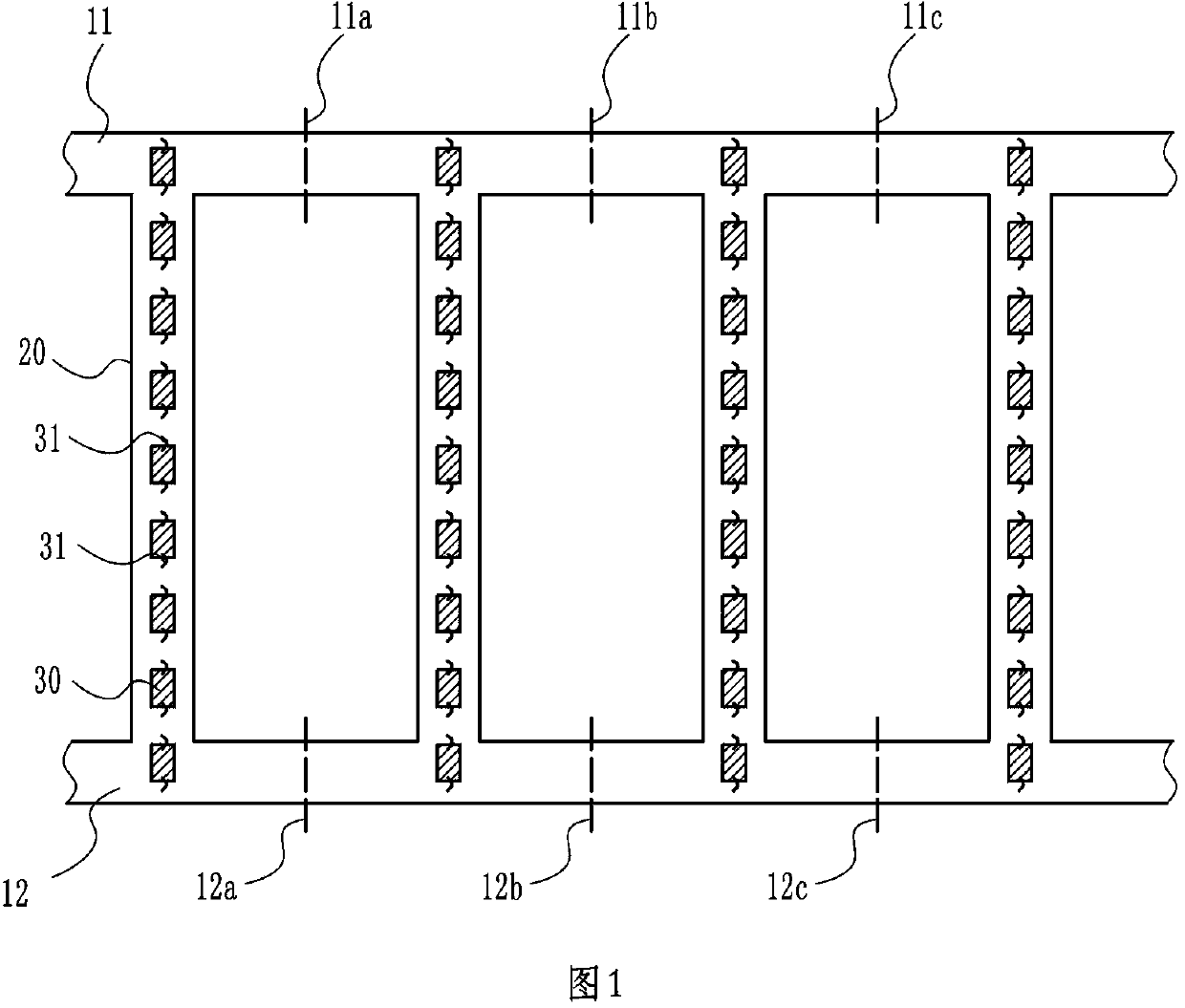
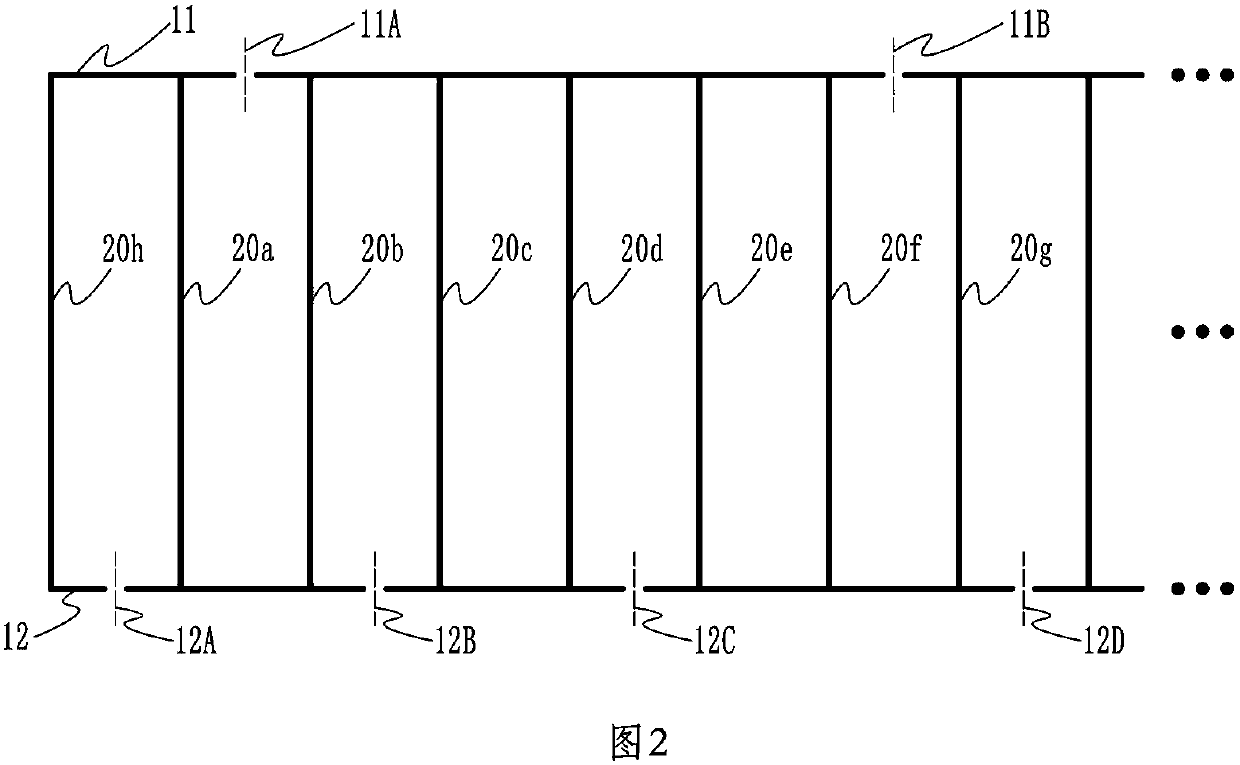
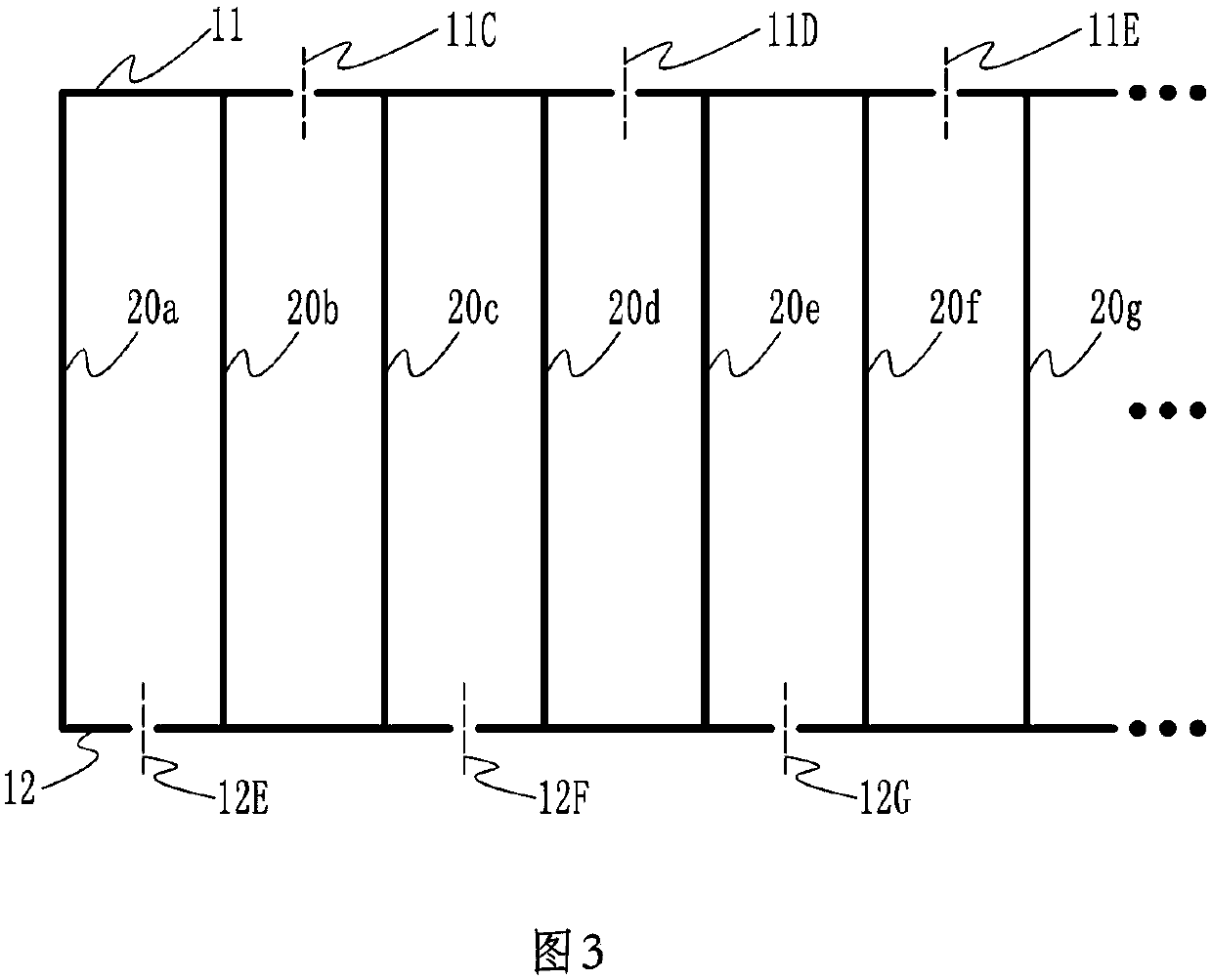
[0033] In order to save space, in this embodiment and other embodiments, the substrate will be represented by a solid line, and the structure of the LED unit and its electrode wires on the substrate will be omitted.

[0034] Such as figure 2 As shown, in this embodiment, the first electrical transverse portion 11 has upper insulating fractures 11A and 11B, and the second electrical transverse portion 12 has lower insulating fractures 12A, 12B, 12C, and 12D. There is an electrical longitudinal portion 20a between the upper insulation fracture 11A and the lower insulation fracture 12A; there is an electrical longitudinal portion 20b between the upper insulation fracture 11A and 12B; the upper insulation fracture 11A and the lower insulation fracture 12A and the lower insulation fracture 12B make the electrical longitudinal A series connection is formed between the portion 20h and the electrical longitudinal portion 20a and the electrical longitudinal portion 20b.

[0035] Ther...

Embodiment 2

[0038] Such as image 3 As shown, in this embodiment, the first electrical transverse portion 11 has upper insulating fractures 11C, 11D, 11E; the second electrical transverse portion 12 has lower insulating fractures 12E, 12F, 12G. In this embodiment, there is only one electrical longitudinal portion between adjacent upper and lower insulating breaks, so that the electrical longitudinal portions 20a, 20b, 20c, 20d, 20e, 20f, 20g are connected in series.

Embodiment 3

[0040] Such as Figure 4 As shown, in this embodiment, the first electrical transverse portion 11 has an upper insulating fracture 11F; the second electrical transverse portion 12 has lower insulating fractures 12H, 12I. In this embodiment, there are only two electrical longitudinal parts between the adjacent upper insulating fracture and the lower insulating fracture, so that the electrical longitudinal parts 20a, 20b, 20c, 20d, 20e, 20f, 20g are connected in parallel and then connected in series.


PUM


Abstract

The invention relates to an LED lamp core combined light source which is formed by combining multiple independent LED lamp cores, and aims at solving problems in LED lamp core fixation and circuit connection as well as problems of being low in yield, high in cost and difficult to popularize. Vertical electrical portions as LED lamp cores are connected via first and second transverse electric portions so that the vertical electrical portions are integrated and the vertical electric portions are uniformly and orderly arranged, thereby avoiding the procedure of assembling LED lamp cores manually, and being high in product consistency, stable in quality and high in yield. Upper and lower insulating fractures are respectively formed in the first and second transverse electrical portions, the amount of the vertical electrical portions between the upper and lower insulating fractures is set to obtain different circuit combinations of the vertical electrical portions, thus, combined LED lamp cores of different specifications can be conveniently made, and the increasing demands can be met.

Description

technical field [0001] The invention relates to LED lighting technology, in particular to an LED wick combined light source composed of a plurality of LED wicks. Background technique [0002] Arrange LED units on a long metal substrate, supplemented by corresponding circuits and fluorescent packaging layers, and a strip-shaped illuminant is the LED wick. Due to the slender shape of the LED wick, the light emitted by a single LED wick is too weak to meet the lighting requirements. In actual use, multiple LED wicks are often used in combination to increase the overall brightness of the light. [0003] At present, the method of combining multiple independent LED wicks faces the problems of fixing and circuit connection of each LED wick. So far, the work of assembling LED wicks has mainly been done manually. Due to the long and narrow size of LED wicks, it is difficult to clamp and assemble, and the precision of manual work is low. The quality of assembly largely depends on th...

Claims


Application Information

Patent Timeline
Patent Type & Authority Applications(China)
IPC IPC(8): H01L25/075H01L33/48H01L33/62
Inventor 廖志勇王闽黄黎帆
Owner 厦门市瀚锋光电科技有限公司
Learn More