Novel intelligent electronic coil

An intelligent and electronic technology, applied to electromagnets, electromagnets with armatures, etc., can solve problems such as control failure, magnetic circuit hysteresis eddy current loss, and action time changes, so as to reduce size and cost, prolong service life, and improve reliability effect

Active Publication Date: 2014-12-03
FUZHOU UNIV
View PDF5 Cites 4 Cited by
  • Summary
  • Abstract
  • Description
  • Claims
  • Application Information

AI Technical Summary

Problems solved by technology

The dispersive characteristics of the action time of the electromagnetic system exist both for AC electromagnetic appliances and for DC electromagnetic appliances, which makes it difficult to control electromagnetic appliances, and the influence is more obvious for electromagnetic circuit breakers that require fast action.
Although the time of the microprocessor control system is within the microsecond level, the dispersion of the action time of the mechanism often leads to control failure, and, with the frequent operation of the switching device, the wear of the contact system, the aging of the mechanism, etc. Will cause the action time to change;
[0009] (3) Narrow working voltage range
[0011] (5) There is hysteresis eddy current loss in the magnetic circuit
For AC electromagnetic appliances, the alternating magnetic field leads to iron loss in the magnetic circuit. Although the iron core structure of silicon steel sheet is used, there is still a large loss, and it brings certain difficulties to product design and magnetic circuit analysis.

Method used


Image

  • Novel intelligent electronic coil
  • Novel intelligent electronic coil

Examples


Embodiment Construction

[0034] The technical solutions of the present invention will be described in detail below with reference to the accompanying drawings.

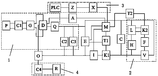
[0035] The present invention provides a new type of intelligent electronic coil, such as figure 1 It is characterized in that it includes: a micro-power processor M, a full-bridge rectifier circuit 1, an excitation coil C, a first switch tube K1 and a freewheeling demagnetization circuit 2; the micro-power processor M The first input end is connected to the output end of the voltage sampling circuit A, and the voltage sampling circuit A is used to sample the instantaneous value of the input voltage to ensure that the exciting coil C starts reliably and provides the required value for calculating the average value of the input voltage during the breaking process. The sampling voltage ensures reliable disconnection of the exciting coil C; the input end of the voltage sampling circuit A is connected to the first output end of the full-bridge rec...


PUM


Abstract

The invention relates to a novel intelligent electronic coil. The novel intelligent electronic coil is characterized in that one output end of a full bridge rectifying circuit is connected into a low power dissipation processor through a voltage sampling circuit, the other output end of the full bridge rectifying circuit is connected with the input end of a self-powered circuit and connected into the output end of a follow current demagnetization loop through one end of an exciting coil, and the reference end is grounded; one output end of the self-powered circuit is connected with one input end of the low power dissipation processor, the other output end of the self-powered circuit is connected to a first driving circuit, the other input end of the low power dissipation processor is connected with a current sampling circuit, one end of the current sampling circuit is connected with reference end of the self-powered circuit and grounded, the other end of the current sampling circuit is connected with a first switch tube, two output ends of the low power dissipation processor are connected into the follow current demagnetization loop and the first switch tube through driving circuits respectively, and the other end of the follow current demagnetization loop is connected with the first switch tube through the other end of the exciting coil. The novel intelligent electronic coil has the advantages of being small in size, wide in voltage input, suitable for both alternating current and direct current, fast to break, reliable in work and the like.

Description

technical field [0001] The invention relates to the field of intelligent control of instruments, in particular to a novel intelligent electronic coil. Background technique [0002] Electromagnetic appliances are devices that use electromagnetic systems for energy conversion, which are mainly composed of magnetic mechanisms and coils. The excitation coil is energized to magnetize the magnetic system to generate electromagnetic attraction to attract the armature, so that it moves to perform mechanical work, so as to achieve the predetermined purpose. Absorbing energy from the power supply through the coil and outputting mechanical work by the movement of the armature is one aspect of the energy conversion of the electromagnetic system. aspect. Electromagnetic systems are widely used, and can be used as a type of electrical appliances alone, such as traction electromagnets, braking electromagnets, lifting electromagnets, electromagnetic clutches, electromagnetic chucks, etc.;...

Claims


Application Information

Patent Timeline
Patent Type & Authority Applications(China)
IPC IPC(8): H01F7/18
Inventor 许志红庄杰榕
Owner FUZHOU UNIV
Why Eureka
Try Eureka