
A solution dehumidification unit

A solution dehumidification and unit technology, applied in the direction of refrigerators, adsorption machines, refrigeration and liquefaction, etc., can solve the problems of high energy consumption, achieve the effects of reducing energy consumption, improving efficiency, and improving social and economic benefits

Inactive Publication Date: 2017-02-15
深圳德洛克斯科技有限公司
View PDF6 Cites 0 Cited by
  • Summary
  • Abstract
  • Description
  • Claims
  • Application Information

AI Technical Summary

Problems solved by technology

[0009] In order to overcome the deficiencies of the prior art, the object of the present invention is to provide a solution dehumidification unit, which can solve the problem of large energy consumption of the existing dehumidification unit

Method used


Image

  • A solution dehumidification unit

Examples


Embodiment Construction

[0038] The present invention will be described in further detail below in conjunction with the accompanying drawings and specific embodiments.

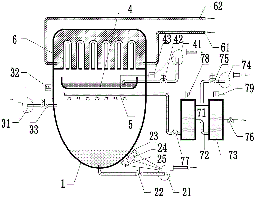
[0039] The present invention as figure 1 As shown, the solution dehumidification unit includes a vacuum boiling evaporation chamber 1, a concentrated solution pump 21, a gas-liquid separation device, an evaporation chamber vacuum pump 31, an evaporation chamber vacuum pressure gauge 32 and a control circuit; Condensing device, condensed water collecting pan 4 and dilute solution sprayer 5 are arranged, the condensing device is arranged on the top of vacuum boiling evaporation chamber 1, the condensed water collecting pan 4 is arranged under the condensing device, and the dilute solution sprayer 5 is arranged on Below the condensed water collection tray 4; the bottom of the vacuum boiling evaporation chamber 1 is provided with a concentrated solution outlet, the concentrated solution outlet is connected with the concentrated solution p...


PUM


Abstract

The invention provides a liquid dehumidification unit applied to the field of heating and ventilating air conditionings and aims to achieve low-pressure normal-temperature regeneration of concentrated liquids. The liquid dehumidification unit comprises a vacuum boiling evaporation chamber, a concentrated liquid pump, a gas-liquid separator, an evaporation chamber vacuum pump, an evaporation chamber vacuum gauge and a control circuit. A condensate collecting tray and a dilute liquid sprayer are disposed within the vacuum boiling evaporation chamber. The bottom of the vacuum boiling evaporation chamber is provided with a concentrated liquid outlet which is connected with the concentrated liquid pump; the control circuit controls the concentrated liquid pump to start or stop. A liquid inlet of the dilute liquid sprayer penetrates the vacuum boiling evaporation chamber to be connected with the gas-liquid separator. The evaporation chamber vacuum pump is communicated with the inside of the vacuum boiling evaporation chamber. The evaporation chamber vacuum gauge is used for detecting interior pressure of the vacuum boiling evaporation chamber. The evaporation chamber vacuum gauge transmits an evaporation chamber pressure detection signal to the control circuit; the control circuit controls the evaporation chamber vacuum pump to start or stop, according to the evaporation chamber pressure detection signal.

Description

technical field [0001] The invention relates to a solution dehumidification unit, in particular to a solution dehumidification unit applied to HVAC. Background technique [0002] The country strongly advocates energy saving and emission reduction, and the energy consumption of HVAC accounts for about 60% of building energy consumption, so the energy saving of HVAC occupies an absolute position in building energy conservation. The use of an independent temperature and humidity control system can greatly improve the efficiency of the air-conditioning host, thereby reducing building energy consumption. The temperature and humidity independent control system has been successfully used in practical engineering applications. The implementation process is to separate the sensible heat and latent heat. The sensible heat is processed by the high-temperature cold water host, and the latent heat is processed by the solution dehumidification equipment. The core of solution dehumidifica...

Claims


Application Information

Patent Timeline
Patent Type & Authority Patents(China)
IPC IPC(8): F25B15/00F24F3/14B01D53/26
Inventor 刘聪彭书涛冯莉华李玉岚
Owner 深圳德洛克斯科技有限公司
Learn More