Clutch device and vibrator for concrete pouring equipped with the same

A technology of clutch device and vibrator, applied in the direction of clutch, mechanical drive clutch, construction, etc., can solve the problems of shaking of driven shaft, unable to provide vibrating rod with driving force, shortening the life of engine or driving motor, etc.

Inactive Publication Date: 2016-05-11
林昌烈
View PDF6 Cites 0 Cited by
  • Summary
  • Abstract
  • Description
  • Claims
  • Application Information

AI Technical Summary

Problems solved by technology

[0010] However, in the existing clutch device, when the driven shaft and the rotating shaft are connected, when the center shaft deviates from the center axis, the driven shaft will shake, thereby shortening the life of the engine or the driving motor, and making the vibration transmission to the The rotating shaft cannot effectively provide the driving force to the vibrating rod, resulting in a significant reduction in work efficiency

Method used


Image

  • Clutch device and vibrator for concrete pouring equipped with the same
  • Clutch device and vibrator for concrete pouring equipped with the same
  • Clutch device and vibrator for concrete pouring equipped with the same

Examples


Embodiment Construction

[0022] Preferred embodiments of the present invention will be described below with reference to the drawings.

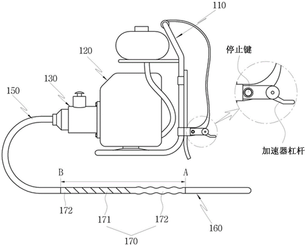
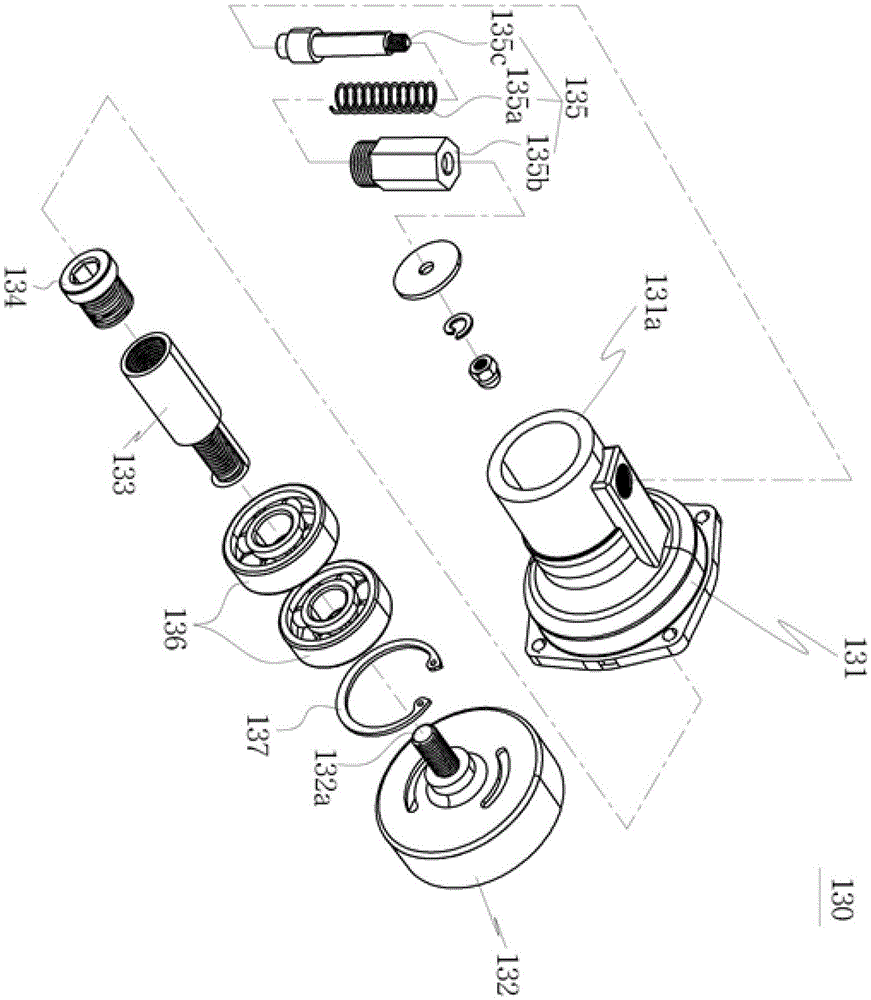
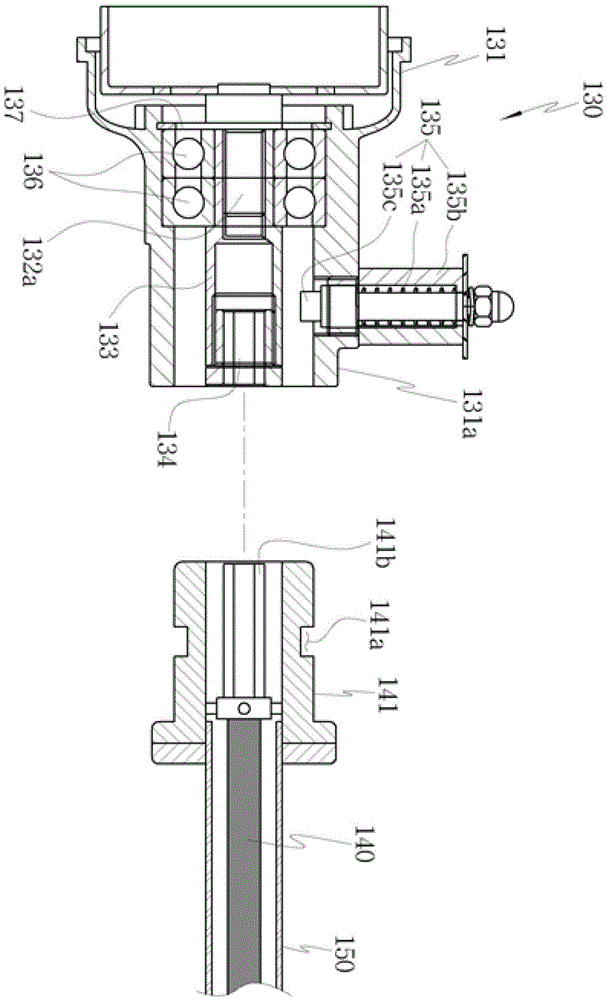
[0023] figure 1 It is a schematic diagram of a vibrator for concrete pouring with a clutch device according to a preferred embodiment of the present invention; figure 2 for display figure 1 An exploded cross-sectional view of the clutch device of the vibrator for concrete pouring;

[0024] image 3 with Figure 4 are displayed respectively figure 2 Combination diagram of the clutch device.

[0025] Such as Figure 1 to Figure 4 As shown, the concrete pouring vibrator of the preferred embodiment of the present invention includes: a main body 110, which is composed of a shoulder strap and a fuel tank that can be carried on the shoulder of the operator; an engine 120, which is formed on the main body 110 , and is activated by the fuel stored in the fuel tank; the clutch device 130, in a state attached to the drive shaft (not shown) of the engine, receives the d...


PUM


Abstract

The invention provides a concrete pouring vibrator. The concrete pouring vibrator comprises a main body, an engine, a clutch device, a connecting hose, a vibrating bar and a metal hose (170), wherein a shoulder band which can be carried on the shoulder part or the back part of an operator and a fuel barrel are formed on the main body; the engine is formed on the main body and is started through fuel stored in the fuel barrel; the clutch device is used for receiving a driving force of a driving shaft so as to generate a rotating force under the condition that the clutch device is arranged on the driving shaft of the engine; the connecting hose is detachably arranged on the clutch device and is internally provided with a flexible wire which is used for receiving the rotating force of the clutch device; the vibrating bar is used for receiving the rotating force supplied by the flexible wire so as to generate vibration under the condition that the vibrating bar is connected to the flexible wire of the connecting hose; the metal hose (170) is used for wrapping the part from a connecting position A of the vibrating bar (160) and the connecting hose (150) to an intermediate position B of the connecting hose (150) and preventing the winding and the breaking off of the connecting hose (150).

Description

technical field [0001] The present invention relates to a clutch device and a vibrator for concrete pouring with the clutch device, in particular to a vibrator that can prevent vibration when the driving force is transmitted through the connection between the engine and the clutch device, thereby prolonging the life of the engine and more effectively transmitting the driving force to the vibrating rod. Driving force, and the operator can carry it on the shoulder, so that the convenience and stability of the operation can be ensured, and the clutch device and the concrete pouring vibrator equipped with the same can improve the work efficiency. Background technique [0002] Generally, a vibrator is used when pouring concrete. After the concrete is mixed well, when the vibration is applied, the movement of the aggregate is proportional to the given vibration acceleration and inversely proportional to its mass. Therefore, the movement range of the large aggregate is small, and t...

Claims


Application Information

Patent Timeline
Patent Type & Authority Patents(China)
IPC IPC(8): F16D23/00F16L3/26E04G21/08
Inventor 林昌烈
Owner 林昌烈
Why Eureka
Try Eureka