
Living cell culture environment control system for microscope

A technology for controlling systems and microscopes, used in enzymology/microbiology devices, bioreactors/fermenters for specific purposes, biochemical instruments, etc., to solve problems such as insufficient temperature control accuracy, limitations, damage to boxes or instruments, etc. , to achieve the effect of eliminating temperature control dead angles and temperature gradients, improving user experience, and quick disassembly and assembly

Active Publication Date: 2014-12-03
UNIV OF SCI & TECH OF CHINA
View PDF9 Cites 0 Cited by
  • Summary
  • Abstract
  • Description
  • Claims
  • Application Information

AI Technical Summary

Problems solved by technology

The first type of system is small in size, and the biggest problem is that the accuracy of temperature control is not enough; secondly, due to the temperature difference between the inside and outside of the culture chamber cover, there will be condensed water, which seriously affects the observation effect of DIC and transmitted light; thirdly, due to the The upper cover of the cultivation room has temperature control wiring, and the shadow will affect the effect of multi-point shooting
The second type of system, due to its large size, heavy weight, and complicated installation, is generally suitable for a living cell workstation system with specific functions. If not, it needs to be disassembled frequently, and this kind of operation has a great risk of damaging the box or the instrument
[0004] In summary, the above two commonly used living cell environment control systems are subject to certain limitations in application adaptability due to their respective structures.

Method used


Image

  • Living cell culture environment control system for microscope
  • Living cell culture environment control system for microscope
  • Living cell culture environment control system for microscope

Examples


Embodiment Construction

[0023] Examples of the present invention are described below. But the following examples are limited to explain the present invention, and the protection scope of the present invention should include the whole content of claim, and through following embodiment, those skilled in the art can realize the whole content of claim of the present invention.

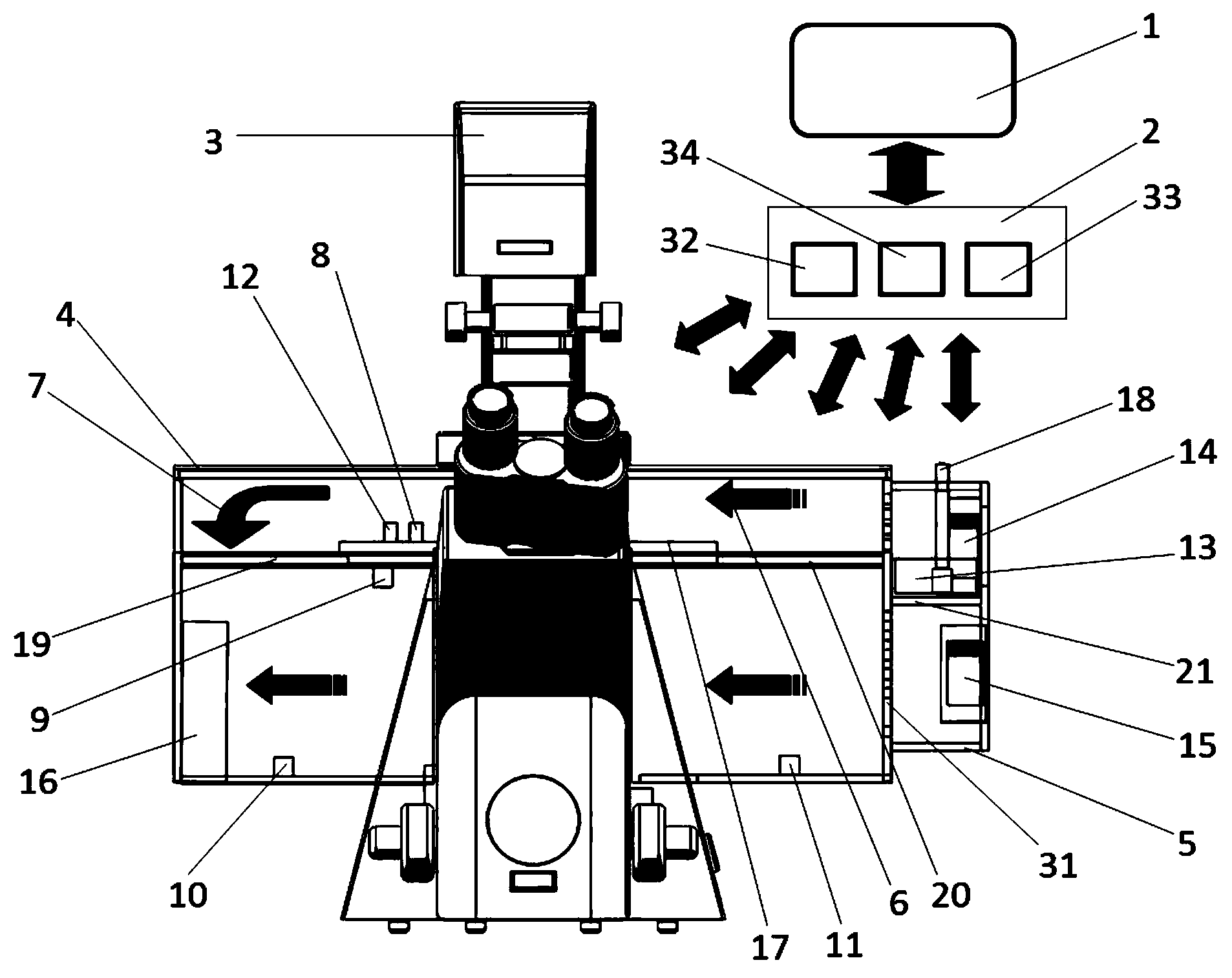
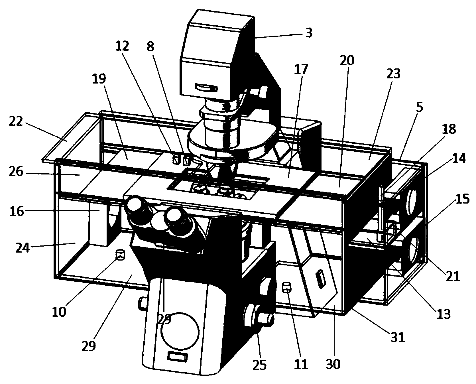
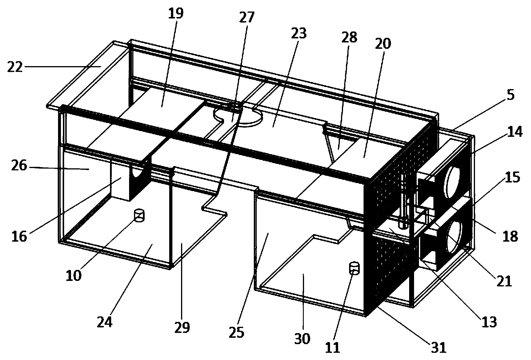
[0024] like figure 1 As shown, the living cell culture environment control system of the present invention is composed of a host computer 1, a controller 2, an incubator 4 and an integrated actuator 5, and the incubator 4 box includes a left top plate 22, a right top plate 23, and a left panel 24. Right panel 25, left panel 26, left back panel 27, right back panel 28, left RTO glass bottom panel 29, right RTO glass bottom panel 30; the right side of the incubator 4 through the porous plate 31 integrated actuator 5 In one body; the left top plate 22, right top plate 23, left panel 24, right panel 25, left back panel 27, right bac...


PUM


Abstract

The invention relates to a living cell culture environment control system for a microscope. The control system comprises a host computer, a controller, an incubator and an integrated actuator, wherein the host computer can be used for setting temperature and CO2 concentration; the temperature can be separately set and controlled point by point; the incubator has a laminar flow air supply structure of which the upper layer and the lower layer independently work; a top plate of the incubator is arranged above a microscope stage and below a collecting lens turntable, and can be opened and closed towards two sides; the controller comprises a multi-point temperature controller and a CO2 concentration controller; temperature detecting probes are respectively arranged above and below the microscope stage and on a left bottom plate and a right bottom plate of the incubator; in combination with the CO2 concentration above the microscope stage, the temperature is controlled at the lower layer and the temperature and the CO2 concentration can be simultaneously controlled at the upper layer. The integrated actuator is of an integral structure with heating, humidifying and CO2 mixing functions. The living cell culture environment control system is simple in mechanism, easy to operate, and small in size, can be quickly disassembled and assembled, and has good control accuracy, and the function of the high-performance microscope is given a full play.

Description

technical field [0001] The invention relates to a living cell culture environment control system for a microscope, which belongs to the technical field of cell imaging. Background technique [0002] Live cell imaging is a research method to observe the movement changes of the internal structure of cells and the physiological process of cells through real-time dynamic or image acquisition over a period of time. On the one hand, live cell imaging needs to maintain the physiological activity of cells, and on the other hand, it can use a microscope for real-time observation and image acquisition, so it needs the support of a cell culture environment control system. A cell culture environment control system is an essential component for live cell imaging. In the absence of medium or suitable temperature and other conditions, animal cells can usually only maintain normal activities for a short period of time. Therefore, to achieve live cell imaging on a microscope, it is necessa...

Claims


Application Information

Patent Timeline
IPC IPC(8): C12M1/38C12M1/36C12M1/34C12M1/04
CPCC12M41/12C12M41/14C12M41/34C12M41/36C12M41/48
Inventor 吴旭周江宁何海辉程新萍刘振邦王黎丽刘雅静孙红娟
Owner UNIV OF SCI & TECH OF CHINA
Learn More