
Guide conveying mechanism for lock tongue

A technology of conveying mechanism and guiding mechanism, applied in the field of machining, can solve the problems of difficulty in guaranteeing the dimensional accuracy of the lock tongue, low material utilization rate, low work efficiency, etc., and achieves the effects of compact structure, easy operation and improved work efficiency.

Inactive Publication Date: 2016-03-30
GUANGXI SHENGLONG METALLURGICAL CO LTD
View PDF5 Cites 0 Cited by
  • Summary
  • Abstract
  • Description
  • Claims
  • Application Information

AI Technical Summary

Problems solved by technology

The shape of the lock tongue has square tongue, oblique tongue, knuckle and other shapes. In the prior art, the processing of oblique tongues is usually done manually one by one. The process is cumbersome, the work efficiency is low, the dimension accuracy of the lock tongue is difficult to guarantee, and the material utilization rate is low.

Method used


Image

  • Guide conveying mechanism for lock tongue
  • Guide conveying mechanism for lock tongue
  • Guide conveying mechanism for lock tongue

Examples


Embodiment Construction

[0015] The specific implementation manner of the present invention will be described below in conjunction with the accompanying drawings.

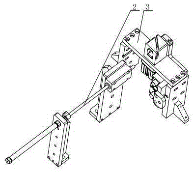
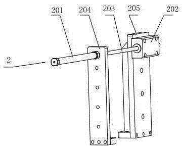
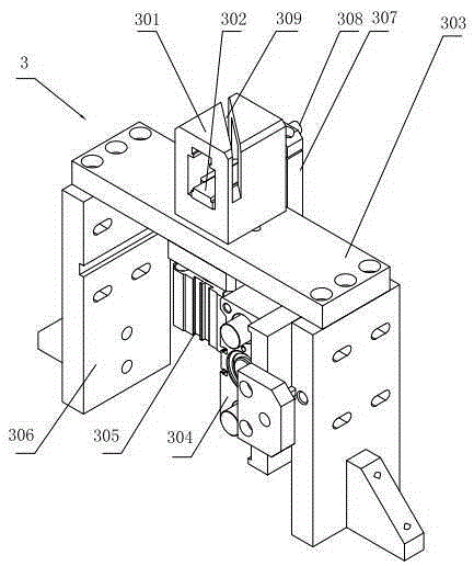
[0016] Such as figure 1 As shown, the guide conveying mechanism for the deadbolt of the present embodiment includes a deadbolt clamping mechanism 3, and one end of the deadbolt clamping mechanism 3 is equipped with a guiding mechanism 2, such as image 3 with Figure 4 As shown, the structure of the deadbolt clamping mechanism 3 is as follows: comprising supporting frames 306 arranged at intervals, a bottom plate 303 is fixed on the top of the supporting frame 306, a deadbolt clamping block 301 is fixed on the bottom plate 303, and the dead bolt clamping block 301 forms The cuboid structure is located in the middle of the bolt clamping block 301 and has a through hole passing through the bolt. The lifting cylinder 305, the output end of the lifting cylinder 305 is fixedly connected with the moving block 302; the moving block 302 can move...


PUM


Abstract

A guiding and conveying mechanism for bolts comprises a bolt clamping mechanism. A guide mechanism is mounted at one end of the bolt clamping mechanism and structurally comprises support frames arranged at an interval, a bottom plate is fixed at the top of the support frame, a bolt clamping block which is of a rectangular structure is fixed on the bottom plate, a through hole penetrating the bolts is formed in the position of the middle of the bolt clamping block, a moving block is mounted on the lower portion of the through hole, and a helical cutter groove is formed in the upper end of the bolt clamping block; a lifting cylinder is mounted at the position located at the bottom of the bottom plate, and the output end of the lifting cylinder is fixedly connected with the moving block; a discharging cylinder is fixed on the inner side wall of the support frame with the output end connected with a fixing plate, a first guide rod is mounted on the fixing plate, and the head of the first guide rod is in butt joint with the bolts. Under the cooperative function of the guide mechanism and the bolt clamping mechanism, the bolts can be conveniently guided and conveyed; the guiding and conveying mechanism can be conveniently applied to assembly line processing so as to improve working efficiency.

Description

technical field [0001] The invention relates to the technical field of machining, in particular to a guiding and conveying mechanism for a lock tongue. Background technique [0002] The lock tongue is the basic component of the lock. The lock relies on the lock tongue to connect the lock body and the lock tongue box to play an anti-theft function. Rotating the lock cylinder can drive the lock tongue to expand and contract to control the switch of the lock body. The shape of the lock tongue includes square tongue, oblique tongue, knuckle and other shapes. In the prior art, the processing of oblique tongues is usually done manually one by one. Contents of the invention [0003] Aiming at the above-mentioned shortcomings in the existing production technology, the applicant provides a guiding and conveying mechanism for lock tongues with a reasonable structure, so that it can be easily applied in assembly line processing, improve the reliability of use, and improve work effici...

Claims


Application Information

Patent Timeline
Patent Type & Authority Patents(China)
IPC IPC(8): B65G21/20
Inventor 董仲伟
Owner GUANGXI SHENGLONG METALLURGICAL CO LTD
Learn More