Device and method for assembling steelwire snap ring in piston

A steel wire clip and piston technology, applied in metal processing, metal processing equipment, manufacturing tools, etc., can solve problems such as affecting the assembly quality, scratching the inner wall of the piston hole by the wire port, and only staying on the top of the piston hole. Low, high-quality press-fit, practical effect

Active Publication Date: 2014-12-03
COMAU SHANGHAI ENG
View PDF6 Cites 5 Cited by
  • Summary
  • Abstract
  • Description
  • Claims
  • Application Information

AI Technical Summary

Problems solved by technology

Its disadvantage is that due to the limited size of the workpiece, the tapered sleeve cannot extend into the piston hole and can only stay above the piston hole. In this way, when the steel wire circlip enters the piston hole through the tapered hole, due to the tension , will make the sharper steel wire port scratch the inner wall of the piston hole and affect the assembly quality

Method used


Image

  • Device and method for assembling steelwire snap ring in piston
  • Device and method for assembling steelwire snap ring in piston
  • Device and method for assembling steelwire snap ring in piston

Examples


Embodiment

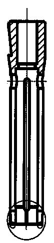
[0033] Such as figure 1 As shown, it is a schematic structural diagram of the device for assembling the piston steel wire circlip. The described device for assembling the piston steel wire circlip includes a taper sleeve 5 and a feeding mechanism 3 capable of sending the steel wire circlip 4 to the taper sleeve 5, above the taper sleeve 5 There is a center pin 1 and an elastic pressure head 2, the center pin 1 and the elastic pressure head 2 are independent, and can slide up and down relative to each other, and a fixed seat 6 for placing the piston and supporting the piston connecting rod is provided under the taper sleeve 5, such as figure 2 As shown, the fixed seat 6 is provided with a lower ejector rod 7 that can move up and down and can hold the steel wire clamp together with the piston pin. When the piston is placed on the fixed seat 6, the piston is positioned by the lower push rod 7.

[0034] Such as Figure 4 As shown, there is a gap between the taper sleeve 5 and t...


PUM


Abstract

The invention provides a device and a method for assembling a steelwire snap ring in a piston. The device is characterized by comprising a taper sleeve and a feeding mechanism capable of feeding the steelwire snap ring into the taper sleeve; a center pin and an elastic pressure head are arranged above the taper sleeve and can move up and down relative to each other; a fixed seat for placing a piston and supporting a piston connecting rod is arranged below the taper sleeve; a downward jacking rod which can move up and down and clasp the steelwire snap ring together with a piston pin is arranged in the fixed seat. According to the invention, the inner wall of the piston hole is effectively prevented from being scratched by the tension function of the steelwire snap ring, so that good assembly quality is guaranteed, the device is basically suitable for assembling all steelwire snap ring parts, and is low in cost, strong in practicability and high in press-mounting quality.

Description

technical field [0001] The invention relates to a device and a method for assembling piston steel wire circlips, which are suitable for assembling steel wire circlips, especially in the automobile powertrain assembly line industry. Background technique [0002] The piston pin of the engine is kept in the piston by a steel wire circlip. The commonly used press-fitting method is based on the principle of using the elastic pressure head and the taper sleeve to shrink the steel wire circlip in place first, and then press it into the piston hole. in the snap ring groove. The feeding mechanism pushes the steel wire circlip in the original state into the hole of the taper sleeve; the center guide pin goes down first, and uses the taper hole in the center of the piston pin to guide the position of the piston to ensure that the piston hole is coaxial with the press-fitted taper sleeve; the elastic pressure claw goes down, Push the steel wire circlip through the taper sleeve and ente...

Claims


Application Information

Patent Timeline
Patent Type & Authority Applications(China)
IPC IPC(8): B23P19/04
CPCB23P19/027
Inventor 王清燕
Owner COMAU SHANGHAI ENG
Why Eureka
Try Eureka