A Mesh Coordinated Forming Method for Superplastic Forming/Diffusion Bonding Four-Layer Structures

A technology of diffusion joining and superplastic forming, applied in the field of thin-walled structure forming technology, can solve the problem of inconsistent mesh forming degree and achieve the effect of coordinated forming

Active Publication Date: 2016-08-24
AEROSPACE RES INST OF MATERIAL & PROCESSING TECH +1
View PDF6 Cites 2 Cited by
  • Summary
  • Abstract
  • Description
  • Claims
  • Application Information

AI Technical Summary

Problems solved by technology

[0005] like image 3 What is shown is a typical part with this structure. Taking this part as an example, if the main air intake path is placed on the edge of No. 2 grid, the No. 2 grid will be deformed preferentially after the air intake, and the No. 7 grid which is farther away from it will be deformed first. , No. 9 grid must be deformed later, which may cause the final forming degree of these grids to be inconsistent

Method used


Image

  • A Mesh Coordinated Forming Method for Superplastic Forming/Diffusion Bonding Four-Layer Structures
  • A Mesh Coordinated Forming Method for Superplastic Forming/Diffusion Bonding Four-Layer Structures
  • A Mesh Coordinated Forming Method for Superplastic Forming/Diffusion Bonding Four-Layer Structures

Examples


Embodiment 1

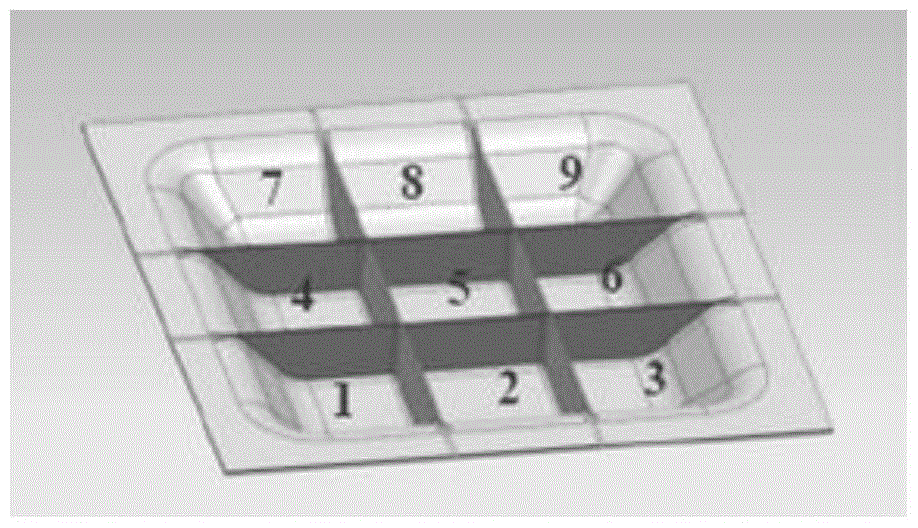
[0062] Taking the superplastic forming / diffusion connection of a square four-layer thin-walled structural part with nine meshes as an example, mesh coordinated forming is performed. The specific process is as follows, such as Figure 4 Shown:

[0063] Step 1. Set the position of the main intake air path

[0064] Set the main intake air path at the edge center of the No. 2 grid in the middle of one side of the part;

[0065] Step 2. Sort all the grids according to the distance from the main gas path

[0066] According to the distance from the main intake air path, the grids are sorted from No. 1 to No. 9. The number of grids passing through from the main intake air path to the target grid is n, and n is a natural number, that is

[0067] The number of grids passing through from the main intake gas path to grid No. 2 is n=0,

[0068] The number of grids passing through from the main intake gas path to grids 1, 3 and 5 n=1,

[0069] The number of grids passing through from t...

Embodiment 2

[0080] Taking the superplastic forming / diffusion connection of a rectangular four-layer thin-walled structural part with 24 meshes as an example, mesh coordinated forming is performed. The specific process is as follows, such as Figure 5 Shown:

[0081] Step 1. Set the position of the main intake air path

[0082] Set the main intake air path at the edge center of the No. 3 grid in the middle of the longer side of the part;

[0083] Step 2. Sort all the grids according to the distance from the main gas path

[0084] According to the distance from the main intake air path, the grids are sorted from No. 1 to No. 24. The number of grids passing through from the main intake air path to the target grid is n, and n is a natural number, that is

[0085] The number of grids passing through from the main intake gas path to grid No. 3 n=0,

[0086] The number of grids passing through from the main intake gas path to grids 2, 4 and 9 is n=1,

[0087] The grid number n=2 is the numb...


PUM


Abstract

The invention provides a superplastic forming/diffusion bonding grid coordinated forming method of a four-layer structure. The method comprises the followings steps: step I, setting the position of a main air inlet air course; step II, sequencing all grids according to the distance from the main air inlet air course to each grid; step III, setting the width of each grid air course; step IV, air intake forming. By adopting the method, in the process that a core veneer forms the grids, the air course route of the grid which is far away from the main air inlet air course is more direct, and the expansion beginning time of the grids with different distances to the main air inlet air course get close to each other as far as possible. The width of the air inlet air course of the grid which is farther away from the main air inlet air course is greater, the air is rapider to feed, the width of the air inlet air course of the grid which is nearer to the main air inlet air course is smaller, the air is slow to feed, the forming degree of the grids on different positions is also enabled to be close to each other as far as possible on the aspect of the air intake speed, and the coordinated forming can be realized.

Description

technical field [0001] The invention relates to a thin-walled structure forming process, in particular to a grid coordination forming method of a superplastic forming / diffusion connection four-layer structure. Background technique [0002] The superplastic forming / diffusion bonding process is usually applied to the forming of sheet metal, and thin-walled grid parts with four-layer structure can be formed by relying on this process (such as attached figure 1 As shown), this structure has the advantages of thin wall and light weight, and can be applied to the manufacture of rudder wing parts of aerospace vehicles to meet the weight reduction requirements of the structure. [0003] The process is achieved by superplastic forming and local diffusion joining of four-layer sheet metal blanks using air pressure in the part mold cavity at high temperature. Among the four-layer sheets, the outer one is the panel, which finally forms the skin of the part; the inner one is the core pl...

Claims


Application Information

Patent Timeline
Patent Type & Authority Patents(China)
IPC IPC(8): B21D26/021
Inventor 高鹏阴中炜微石张绪虎石刚单群
Owner AEROSPACE RES INST OF MATERIAL & PROCESSING TECH
Why Eureka
Try Eureka