Busbar device with noise filter
一种噪声滤波器、汇流条的技术,应用在全封闭母线装置、变压器/电感的零部件、电感器等方向,能够解决通用性低等问题,达到容易使用操作的效果
- Summary
- Abstract
- Description
- Claims
- Application Information
AI Technical Summary
Problems solved by technology
Method used
Image

Examples
no. 1 approach
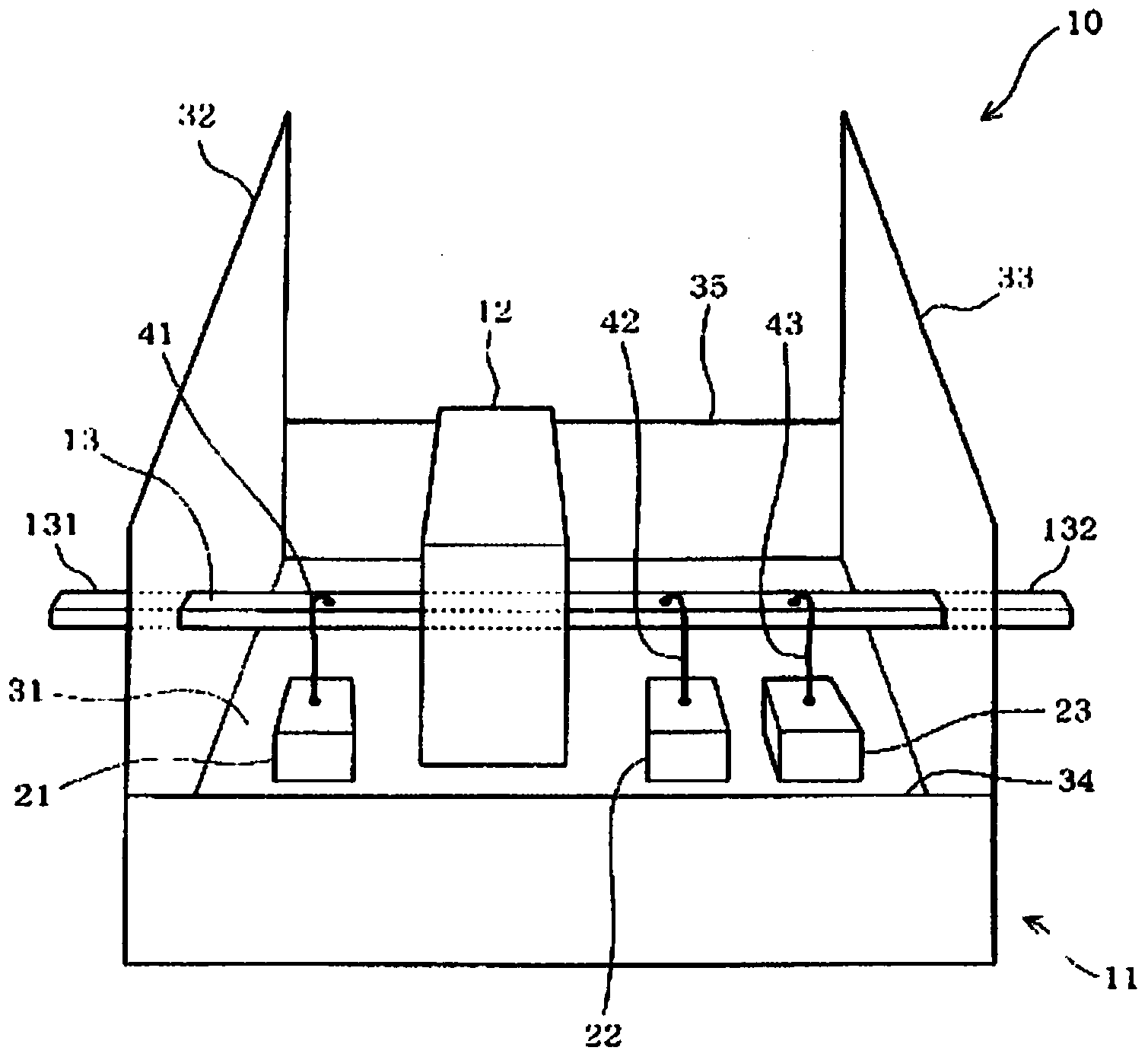
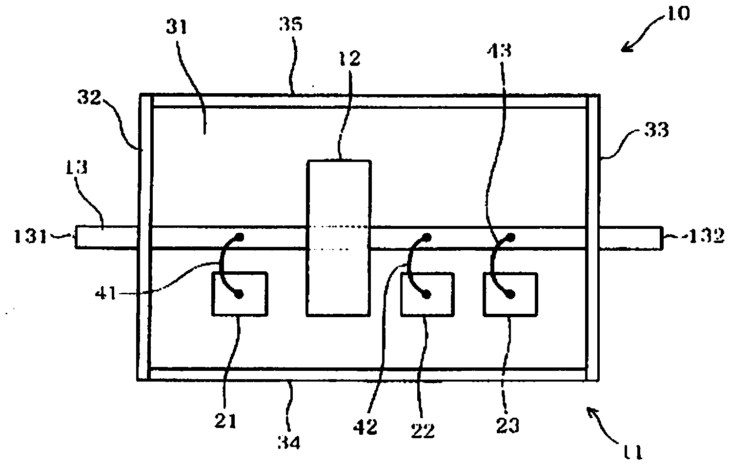
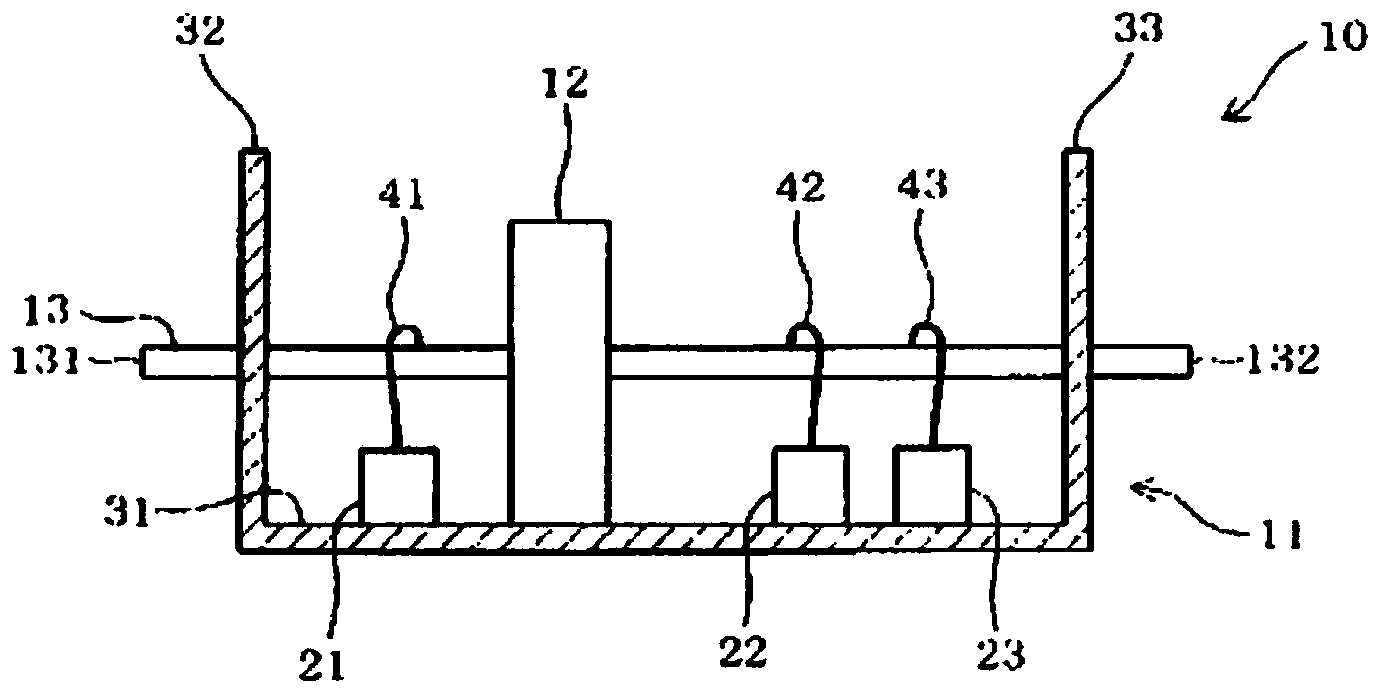
[0031] like figure 1 as well as figure 2 As shown, the bus bar device 10 of the first embodiment is installed in a conductor such as a casing 11 . The bus bar device 10 includes a ferrite core 12 as a magnetic body, a bus bar 13 , a first capacitor 21 , a second capacitor 22 , and a third capacitor 23 . The casing 11 is made of, for example, a conductive metal such as aluminum or an alloy, and is formed in a box shape. The box-shaped casing 11 has a bottom 31 , an input frame portion 32 , an output frame portion 33 , a side frame portion 34 , and a side frame portion 35 . The bottom 31 is formed in a rectangular plate shape such as a rectangle, for example. The bottom 31 corresponds to a ground conductor plane. In the case of the present embodiment, the casing 11 is used as the conductor forming the ground conductor surface, but the ground conductor surface is not limited to the casing 11 . For example, instead of the case 11, the bus bar device 10 may be a metal compone...
Embodiment 4
[0045] In all of Embodiment 4, Embodiment 5, Embodiment 6, and Embodiment 7, first capacitor 21 is arranged in the region of side frame portion 34 of bus bar 13 . And, in Figure 7 In the case of the bus bar device 10 of the illustrated fourth embodiment, the second capacitor 22 is arranged in the same region as the first capacitor 21 on the side frame portion 34 side. On the other hand, the third capacitor 23 is arranged in a region on the side of the side frame portion 35 opposite to the first capacitor 21 with the bus bar 13 interposed therebetween. exist Figure 8 In the case of the bus bar device 10 according to the fifth embodiment shown, both the second capacitor 22 and the third capacitor 23 are arranged in an area on the side of the side frame portion 35 opposite to the first capacitor 21 with the bus bar 13 interposed therebetween. exist Figure 9 In the case of the bus bar device 10 of the illustrated sixth embodiment, the second capacitor 22 is arranged in a reg...
no. 2 approach
[0054] like Figure 12 as well as Figure 13 As shown, the bus bar device 50 of the second embodiment includes a ferrite core 51 as a magnetic body, a bus bar 52 , a ground bar 53 , and a dielectric member 54 . The bus bar device 50 is mounted on the ground conductor plane 55 . The ground conductor surface 55 is a case housing the bus bar device 50 similarly to the first embodiment, or a metal component or the like exposed to the environment where the bus bar device 50 is installed.
[0055] The bus bar 52 is formed of, for example, a conductive metal or alloy such as copper or aluminum. The bus bar 52 has an input end 56 and an output end 57 . The bus bar 52 penetrates the ferrite core 51 from the input side toward the output side. The input end 56 of the bus bar 52 is connected to a power supply (not shown) or the like. On the other hand, an output end portion 57 of the bus bar 52 is connected to a load such as a motor (not shown). In this way, the bus bar 52 connects ...
PUM
 Abstract
Description
Claims
Application Information
 - R&D
- Intellectual Property
- Life Sciences
- Materials
- Tech Scout
- Unparalleled Data Quality
- Higher Quality Content
- 60% Fewer Hallucinations
Browse by: Latest US Patents, China's latest patents, Technical Efficacy Thesaurus, Application Domain, Technology Topic, Popular Technical Reports.
© 2025 PatSnap. All rights reserved.Legal|Privacy policy|Modern Slavery Act Transparency Statement|Sitemap|About US| Contact US: help@patsnap.com