a filling valve
A technology for filling valves and valve bodies, which is applied in packaging, sliding valves, valve devices, etc. It can solve the problems of not being able to ensure the close fit between the slope and the chamfer, the liquid outlet is not closed tightly, and the normal exhaust is affected. The air is not affected, the exhaust is smooth, and the effect of easy assembly and disassembly
- Summary
- Abstract
- Description
- Claims
- Application Information
AI Technical Summary
Problems solved by technology
Method used
Image
Examples
Embodiment 1
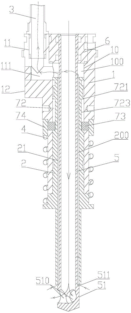
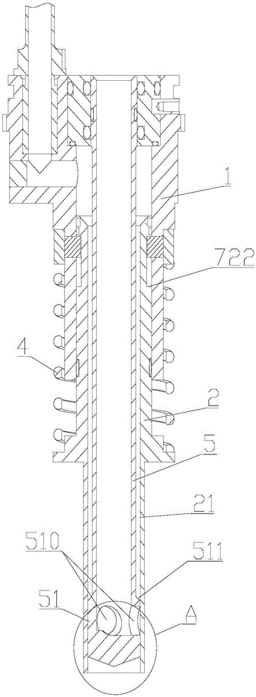
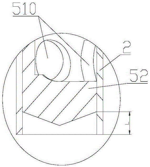
[0030] Such as Figures 1 to 7 Shown is an embodiment of a filling valve of the present invention, which includes a valve body 1, a valve sleeve 2 and an exhaust pipe 3, the valve body 1 has a valve cavity 10, the valve sleeve 2 has an axial through hole 21, and the shaft The through hole 21 is a round hole, the top of the valve sleeve 2 extends into the valve cavity 10, the bottom end of the valve sleeve 2 is located outside the valve body 1, and there is a valve between the valve sleeve 2 and the valve body 1 for driving the valve sleeve 2 and the valve body. The spring 4 of body 1 back movement, the upper end of spring 4 is positioned by the step position of valve body 1 outer side wall, and the lower end of spring 4 is then positioned by the projection body lower end of valve sleeve 2 outer side wall. The outer wall of the valve body 1 has a protruding portion 12. The protruding portion 12 can be a block structure and is molded together with the valve body 1. The upper end...
Embodiment 2
[0039] Such as Figure 8 As shown, the structure of the filling valve is basically the same as that of Embodiment 1, the difference is that the limit block 73 is fixed in the limit groove 72 of the valve sleeve 2, and the installation hole 71 has a certain Length, in the natural state, the limit block 73 is in contact with the top side wall of the mounting hole 71, and as the valve sleeve moves toward the valve body, the limit block 73 gradually approaches the bottom wall of the mounting hole 71, and the end surface of the shaft shoulder After 511 is exposed outside the bottom end of the valve sleeve, the limit block 73 contacts the bottom side wall of the mounting hole 71, and the valve sleeve stops moving relative to the valve body.
PUM
 Abstract
Description
Claims
Application Information
 - R&D
- Intellectual Property
- Life Sciences
- Materials
- Tech Scout
- Unparalleled Data Quality
- Higher Quality Content
- 60% Fewer Hallucinations
Browse by: Latest US Patents, China's latest patents, Technical Efficacy Thesaurus, Application Domain, Technology Topic, Popular Technical Reports.
© 2025 PatSnap. All rights reserved.Legal|Privacy policy|Modern Slavery Act Transparency Statement|Sitemap|About US| Contact US: help@patsnap.com


