Derailment-preventing train connection device
A connecting device and anti-derailment technology, which is applied in transportation and packaging, railway car body parts, railway couplings, etc., can solve problems such as jitter, left and right traction cannot automatically maintain balance, derailment, etc., and achieve the effect of reducing jitter
- Summary
- Abstract
- Description
- Claims
- Application Information
AI Technical Summary
Problems solved by technology
Method used
Image

Examples
Embodiment 1
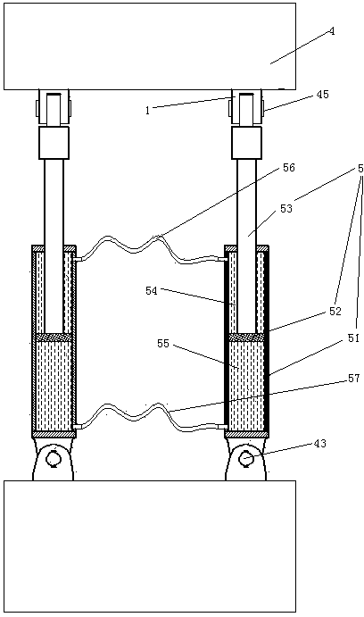
[0028] Embodiment one, see figure 1 , an anti-derailment train connecting device, comprising a pair of sleepers 4 and a pair of connecting cylinders 5. A pair of bolster bars 4 are distributed along the front and rear directions. A pair of tie bars 4 are only connected together by a pair of connecting cylinders 5 .
[0029] A pair of connecting oil cylinders 5 are distributed along the left and right directions. The connecting cylinder 5 includes a cylinder body 51 , a piston 52 and a connecting rod 53 . One end of the cylinder body 51 is hinged to one of the pair of tie rods 4 through the first hinge shaft 43 . The first hinge shaft 43 extends along the vertical direction. The piston 52 is located inside the cylinder 51 . The piston 52 divides the cylinder body 51 into a front oil chamber 54 and a rear oil chamber 55 . One end of the connecting rod 53 stretches into the cylinder from the other end of the cylinder body 51 and is connected together with the piston 52. ...
Embodiment 2
[0033] Embodiment two, the difference with embodiment one is:
[0034] see Figure 4 , The middle part of the pillow rod 4 is provided with a connecting rod 42 . A universal support ball 41 and a scraping sleeve 44 are respectively arranged on the left and right ends of the pillow rod. The two scraping sleeves 44 are sheathed on the pair of universal support balls 41 in one-to-one correspondence.
[0035] see Figure 5 , The scraping cover 44 is sealed and fixed on the pillow rod 4 . The universal supporting ball 41 is spherically matched with the pillow rod 4 . The scraper sleeve 44 is spherically fitted with the universal support ball 41 . The scraper sleeve 44 is sealed and sleeved on the universal support ball 41 . A light groove 441 is provided on the mating surface of the scraper sleeve 44 and the universal support ball 41 . The lamp groove 441 extends along the circumferential direction of the scraper cover 44 . A drying lamp 45 is arranged in the lamp groove 44...
Embodiment 3
[0037] Embodiment three, the difference with embodiment two is:
[0038] see Figure 6 , is also provided with a refueling device 3 . The refueling device 3 includes an oil storage tank 31 , an oil outlet channel 32 and a corrosive liquid storage tank 34 . One end of the oil outlet channel 32 is provided with four filler nozzles 322 . The four filler nozzles 322 are butted together with the two front hinge shafts 45 and the two rear hinge shafts 43 in one-to-one correspondence (that is, the oil is delivered to the hinges). The other end of the oil outlet channel 32 is provided with an oil inlet bucket 321 located below the oil storage tank. The corrosive liquid storage tank 34 is affixed together with one of the pair of tie rods 4 . The oil storage tank 31 is higher than the filler nozzle 322 .
[0039] see Figure 7 , The refueling device also includes a ruptured membrane rod 33, a regular rotting type buoy 35 and a guide rod 36.
[0040] The oil storage tank 31 includ...
PUM
 Abstract
Description
Claims
Application Information
 - R&D
- Intellectual Property
- Life Sciences
- Materials
- Tech Scout
- Unparalleled Data Quality
- Higher Quality Content
- 60% Fewer Hallucinations
Browse by: Latest US Patents, China's latest patents, Technical Efficacy Thesaurus, Application Domain, Technology Topic, Popular Technical Reports.
© 2025 PatSnap. All rights reserved.Legal|Privacy policy|Modern Slavery Act Transparency Statement|Sitemap|About US| Contact US: help@patsnap.com