
Intelligent thickness gauge

A technology of intelligent thickness gauge and detection head, which is applied in the direction of instruments, measuring devices, optical devices, etc., can solve the problems of sensor zero drift, difficult online detection, complex structure, etc., and achieve the effect of compact equipment

Active Publication Date: 2014-11-26
HEIXUANFENG SAW IND
View PDF6 Cites 8 Cited by
  • Summary
  • Abstract
  • Description
  • Claims
  • Application Information

AI Technical Summary

Problems solved by technology

The structure of the automatic thickness measuring device is as follows: a sensor base 605 and a displacement sensor 604 arranged above, the problem is that the workpiece needs to be transported to the sensor base 605 through an auxiliary device, and then measured, the structure is relatively Complicated, it is difficult to realize online detection, and it is also difficult to adapt to products of different specifications. When product specifications change, such as workpieces with larger diameters or thicker thicknesses, the structure of auxiliary devices will become very complicated in order to adapt to different specifications.
Furthermore, in the process of processing, the benchmark may be deviated due to the influence of debris generated by grinding, or the zero point of the sensor may drift due to the influence of voltage fluctuation and temperature change, thus affecting the measurement accuracy

Method used


Image

  • Intelligent thickness gauge
  • Intelligent thickness gauge
  • Intelligent thickness gauge

Examples


Embodiment Construction

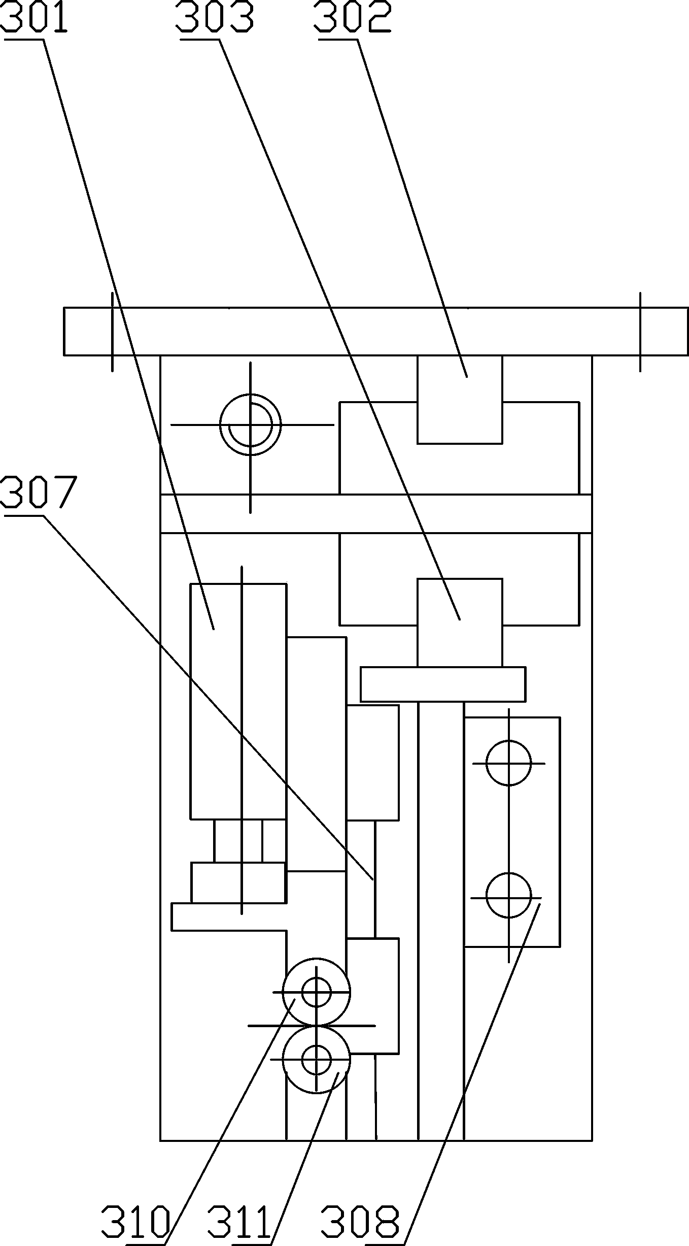
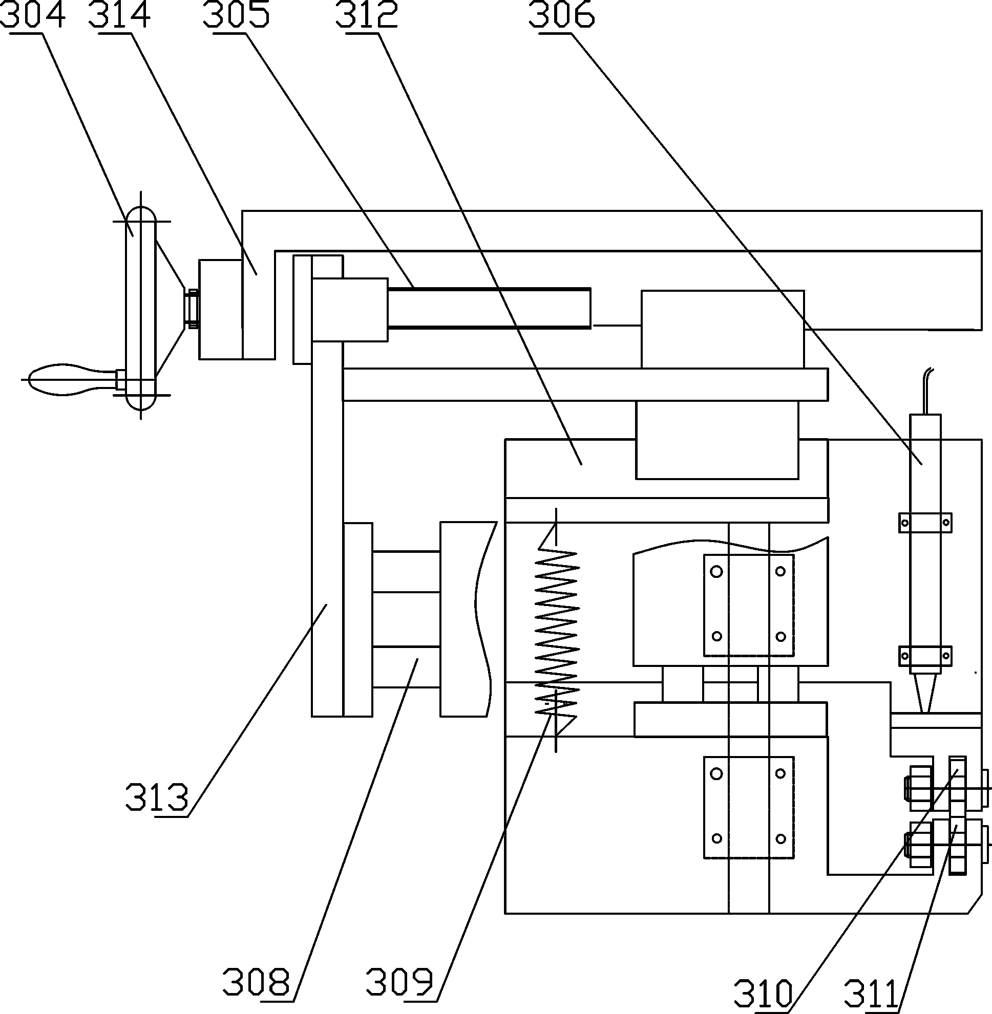
[0024] Such as figure 1 , 2 Among them, an intelligent thickness gauge, the upper detection roller 310 and the lower detection roller 311 are both slidably installed on the detection lifting guide rail 307 through the base; the upper detection roller 310 and the lower detection roller 311 in this example adopt high-precision bearings.

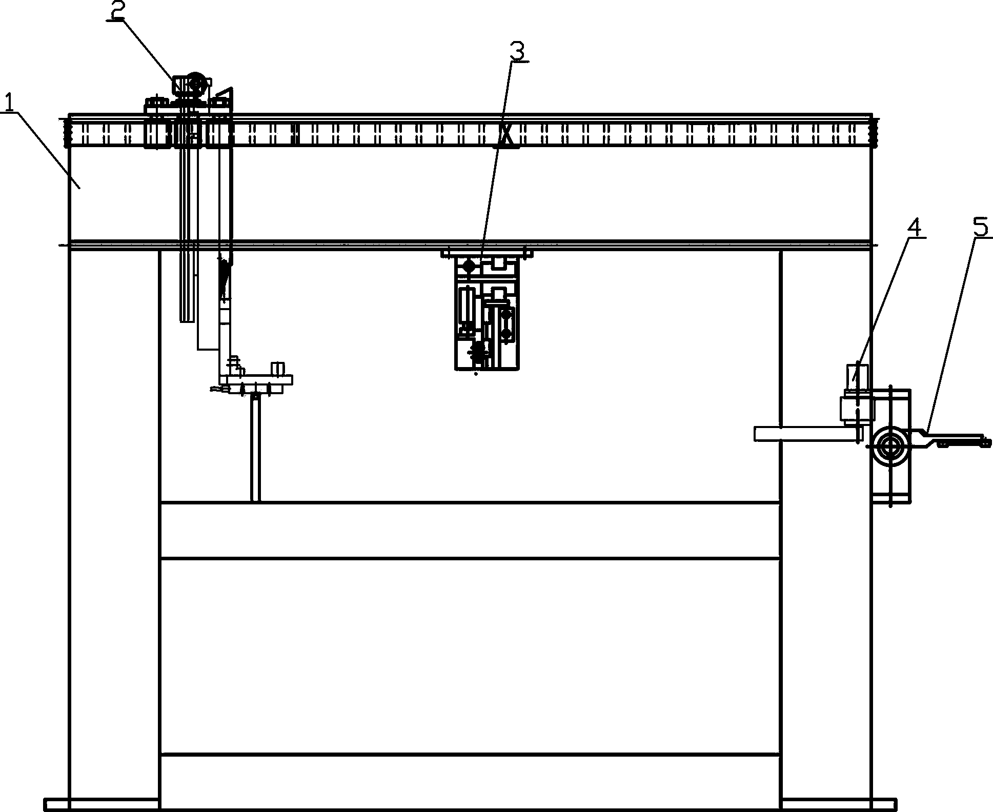
[0025] The base of the upper detection roller 310 and the base of the lower detection roller 311 are installed on the frame by springs, so that the detection point between the upper detection roller 310 and the lower detection roller 311 floats; thus, the structure is adapted to the change of the workpiece thickness specification, That is to say image 3 When the mechanical arm 2 traverses through the thickness detection device 3 of the present invention, the detection point between the upper detection roller 310 and the lower detection roller 311 will change with the position of the lower end of the mechanical arm 2, so it will not be affecte...


PUM


Abstract

The invention discloses an intelligent thickness gauge. An upper detection rolling wheel and a lower detection rolling wheel can both be installed on a detection lifting guide rail in a sliding mode through bases, and the base of the upper detection rolling wheel and the base of the lower detection rolling wheel are installed on a rack through springs so that a detection point between the upper detection rolling wheel and the lower detection rolling wheel can float. The intelligent thickness gauge is further provided with a detection head used for detecting a gap between the upper detection rolling wheel and the lower detection rolling wheel or a gap between the base of the upper detection rolling wheel and the base of the lower detection rolling wheel. A control device connected with the detection head is used for correcting a measurement zero point at any time when the upper detection rolling wheel and the lower detection rolling wheel do not carry out detection. According to the intelligent thickness gauge, because a floating detection point structure is adopted, on-line thickness detection is achieved, in other words, the thickness of a workpiece is directly detected in real time in the production process, and then parameters of grinding machining can be determined according to a detected thickness value. Because the floating detection point structure is adopted, the intelligent thickness gauge can further adapt to changes of thicknesses of workpieces. Because the measurement zero point is corrected at any time, influences caused by sensor zero wander on measurement accuracy are avoided.

Description

technical field [0001] The invention relates to the field of machine tool accessories, in particular to an intelligent thickness gauge for online thickness measurement of batch-type conical workpieces such as flat grinding saw blades. Background technique [0002] In the process of batch workpiece processing of conical shape, there is a large demand for enterprise employees, usually the working environment is poor, the labor intensity is high, and workers cannot operate multiple machines. In the process of work, due to the different thickness of materials, the requirements for finished products are strict, and the requirements for the quality of employees are also high. Today, with the rapid development of economy and technology, traditional grinding machines are becoming less and less suitable for large-scale modern production. [0003] Chinese patent document CN 102328251 A discloses an intelligent horizontal axis circular table surface grinder, which includes a grinding ...

Claims


Application Information

Patent Timeline
IPC IPC(8): B24B49/04G01B21/08
CPCB24B49/04G01B11/06G01B21/08
Inventor 吴滨
Owner HEIXUANFENG SAW IND
Learn More