
Asynchronous motor control method

A technology of asynchronous motor and control method, which is applied in the direction of AC motor control, control system, estimation/correction of motor parameters, etc. Effect

Inactive Publication Date: 2014-11-19
SINOEV TECH
View PDF5 Cites 2 Cited by
  • Summary
  • Abstract
  • Description
  • Claims
  • Application Information

AI Technical Summary

Problems solved by technology

In this case, under light load and small torque, the efficiency of the motor will be greatly reduced.

Method used


Image

  • Asynchronous motor control method
  • Asynchronous motor control method
  • Asynchronous motor control method

Examples


Embodiment Construction

[0038] Embodiments of the present invention are described in detail below, examples of which are shown in the drawings, wherein the same or similar reference numerals designate the same or similar elements or elements having the same or similar functions throughout. The embodiments described below by referring to the figures are exemplary and are intended to explain the present invention and should not be construed as limiting the present invention.

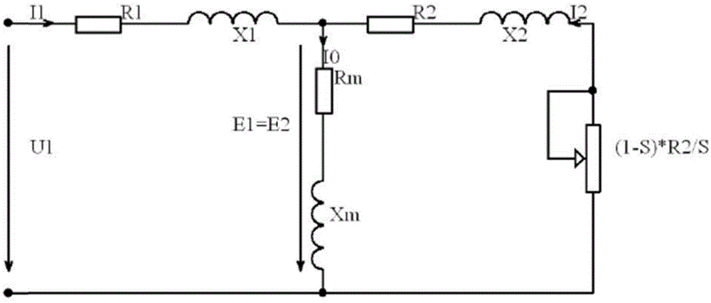
[0039] First refer to the following figure 1 The T-type equivalent circuit of the asynchronous motor is introduced to facilitate the subsequent description of the asynchronous motor control method of the present invention.

[0040] first to figure 1 The various circuit symbols involved in are explained. u 1 is the phase voltage, E 1 is the induced electromotive force on the stator side, E 2 is the induced electromotive force on the rotor side, I 0 is the excitation current, I 1 is the stator current, I 2 is the rotor curr...


PUM


Abstract

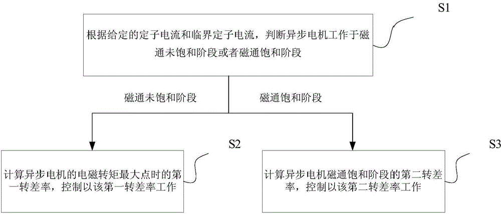
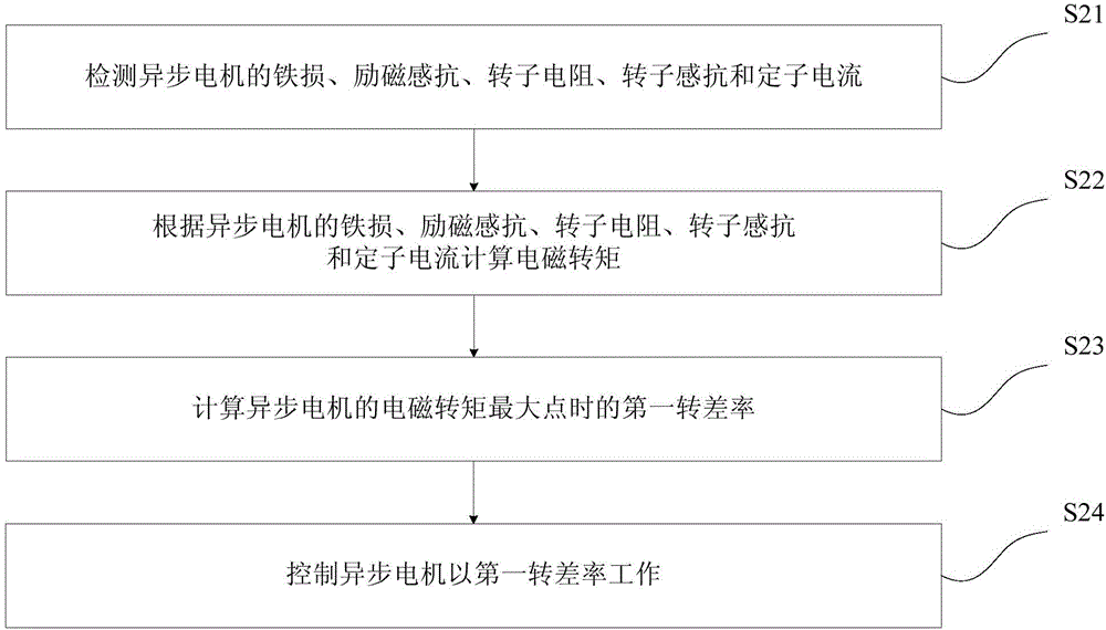
An asynchronous motor control method provided by the present invention comprises the following steps of S1, determining an asynchronous motor works at a magnetic flux unsaturation stage or a magnetic flux saturation stage according to a given stator current and a critical stator current; S2 obtaining a first slip ratio of the asynchronous motor at a maximum electromagnetic torque point, and controlling the asynchronous motor to work at the first slip ratio at the magnetic flux unsaturation stage; S3 calculating a second slip ratio of the asynchronous motor at the magnetic flux saturation stage, and controlling the asynchronous motor to work at the second slip ratio at the magnetic flux saturation stage. According to the present invention, and under a light load small torque, a field current is adjusted dynamically, so that the matching of the field current and a rotor current is at a maximum torque point, at the same time, the maximum torque point is basically an optimum electromagnetic torque point, and accordingly, the energy utilization rate is improved, namely, the efficiency of the motor is improved under the small torque. The method enables the power supply energy consumption to be saved to a large extent when being used in the crowded vehicle condition of an actual city.

Description

technical field [0001] The invention relates to the technical field of motor control, in particular to an asynchronous motor control method. Background technique [0002] Asynchronous motor, also known as induction motor, is an AC motor that generates electromagnetic torque through the interaction of the air gap rotating magnetic field and the induced current of the rotor winding, thereby realizing the conversion of electromechanical energy into mechanical energy. [0003] The existing asynchronous motor speed control system is being used in more and more fields. Generally speaking, these drive systems are required to have a sufficiently wide speed range and fast torque response at the same time. But for some equipment, such as the motor drive of electric vehicles, the energy utilization efficiency is particularly important, so improving the energy utilization efficiency has become an important extension of the field of electric vehicles. [0004] Vehicle asynchronous moto...

Claims


Application Information

Patent Timeline
Patent Type & Authority Applications(China)
IPC IPC(8): H02P23/14H02P25/02
Inventor 关庆斌林尚俊贾建刘茂国
Owner SINOEV TECH
Learn More