
Non-coaxial disc-type magnetic gear

A magnetic gear and disc technology, applied in electrical components, electromechanical devices, etc., can solve the problems of low torque density and low utilization rate of permanent magnets, and achieve a simplified structure, improved energy transfer efficiency, and reduced noise and vibration. Effect

Inactive Publication Date: 2014-11-19
SOUTHEAST UNIV
View PDF6 Cites 8 Cited by
  • Summary
  • Abstract
  • Description
  • Claims
  • Application Information

AI Technical Summary

Problems solved by technology

[0004] Purpose of the invention: Aiming at the above-mentioned prior art, a disc-type magnetic gear with different shafts is proposed, which can solve the problems of low utilization rate of permanent magnets and low torque density in existing magnetic gears with different shafts

Method used


Image

  • Non-coaxial disc-type magnetic gear
  • Non-coaxial disc-type magnetic gear
  • Non-coaxial disc-type magnetic gear

Examples


Embodiment 1

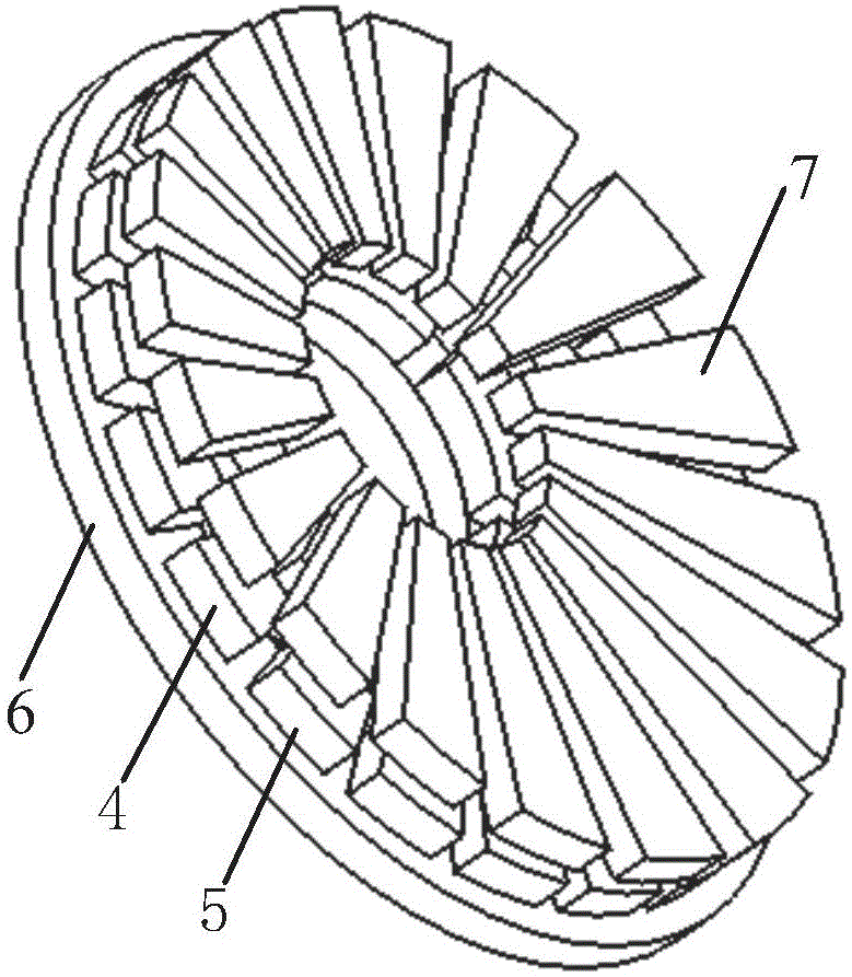
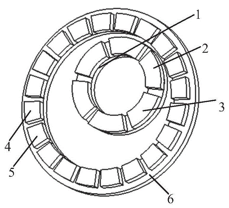
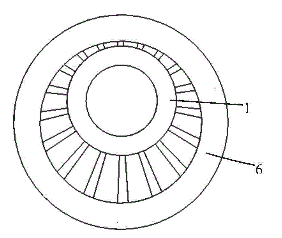
[0017] Embodiment 1: as figure 1 As shown, the disc-type magnetic gear with different axes includes an inner rotor, an outer rotor and a magnetic adjustment structure; both the inner rotor and the outer rotor adopt a disc structure and are placed along different axes, and the inner rotor is placed inside the outer rotor and connected to the outer rotor. The height of the rotor is equal.

[0018] Both the inner rotor and the outer rotor include N-pole permanent magnets and S-pole permanent magnets, and the pole arc coefficients are both 0.6. Wherein, the permanent magnets of the inner rotor have three pairs of poles, and the permanent magnets of the outer rotor have ten pairs of poles. The inner rotor is composed of an N-pole permanent magnet 2 , an S-pole permanent magnet 3 and an inner rotor yoke 1 magnetized in the axial direction. Wherein, the N-pole permanent magnets 2 and S-pole permanent magnets 3 of the inner rotor are interlaced and attached to the surface of the inn...

Embodiment 2

[0021] Embodiment 2: In this embodiment, the difference from Embodiment 1 is only that the N-pole permanent magnet 2 and the S-pole permanent magnet 3 of the inner rotor are embedded in the inner rotor yoke 1; the N-pole permanent magnet 4 of the outer rotor and S pole permanent magnets 5 are embedded in the outer rotor yoke 6 .


PUM


Abstract

The invention provides a non-coaxial disc-type magnetic gear, which can transmit torque and mechanical energy to regulate the relative velocity of an inner rotor and an outer rotor. The non-coaxial disc-type magnetic gear comprises the inner rotor and outer rotor which are not coaxial, and a magnetism-adjusting structure, wherein both the inner rotor and the outer rotor adopt disc-type structures; permanent magnets are axially magnetized and are circumferentially stuck onto the surface of a rotor yoke; the magnetism-adjusting structure consists of magnetism-adjusting iron blocks for guiding magnetism; the magnetism-adjusting iron blocks are placed at intervals; all the magnetism-adjusting iron blocks are fixed together to form the disc-type structures, are placed on one side of each of an inner rotor disc and an outer rotor disc and form certain air gaps with the inner rotor disc and the outer rotor disc. The whole magnetism-adjusting structure is simple in structure and convenient to mount; the non-coaxial disc-type magnetic gear improves the torque density and the energy transfer efficiency by utilizing the magnetic field modulating principle; the non-coaxial disc-type magnetic gear has the advantages of an ordinary magnetic gear of no contact, low noise, overload self-protection and the like, so that the non-coaxial disc-type magnetic gear is especially suitable for non-coaxial transmission, isolated transmission and other occasions.

Description

technical field [0001] The invention relates to a disc-type magnetic gear with different shafts, which is suitable for non-contact variable-speed driving occasions with different shafts, and belongs to the technical field of power transmission. Background technique [0002] In the fields of industrial and agricultural production, national defense, aviation, aerospace and other fields, transmission mechanisms are required to realize power transmission and speed change at the same time. According to different applications, people have developed various conversion devices or equipment to meet the above requirements, such as chains, wire ropes, transmission belts, screw rods, crank connecting rods, slider mechanisms, cam ejector rod mechanisms, etc. In these conversion devices, the transmission mechanisms contact each other, which brings problems such as friction, vibration, noise, etc., and reduces the transmission efficiency of the system and the stability of the transmission ...

Claims


Application Information

Patent Timeline
Patent Type & Authority Applications(China)
IPC IPC(8): H02K16/02
Inventor 付兴贺王标林明耀
Owner SOUTHEAST UNIV
Learn More