
Reconfigurable micro-strip yagi antenna

A technology of Yagi antenna and microstrip, which is applied in the field of reconfigurable microstrip Yagi antenna, can solve the problems of less pattern, lack of effect of pattern scanning, limited scanning of pattern of reconfigurable antenna, etc. Small, enhanced beam deflection, wide variety of effects

Inactive Publication Date: 2014-11-19
UNIV OF ELECTRONICS SCI & TECH OF CHINA
View PDF4 Cites 18 Cited by
  • Summary
  • Abstract
  • Description
  • Claims
  • Application Information

AI Technical Summary

Problems solved by technology

However, the pattern scan of this reconfigurable antenna is limited to the horizontal plane
[0006] In addition, the existing directional pattern reconfigurable antennas can achieve fewer directional patterns, which are far from achieving the effect of pattern scanning

Method used


Image

  • Reconfigurable micro-strip yagi antenna
  • Reconfigurable micro-strip yagi antenna
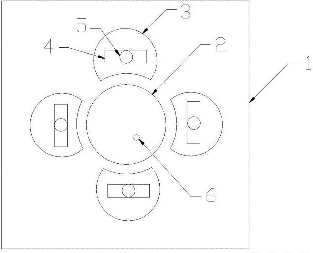
  • Reconfigurable micro-strip yagi antenna

Examples


Embodiment Construction

[0023] The technical solutions of the present invention will be described in detail below in conjunction with the accompanying drawings.

[0024] The reconfigurable microstrip Yagi antenna of the present application includes a dielectric substrate 1, a ground plate and a radiation patch group, the ground plate is located on the lower surface of the dielectric substrate 1, the ground plate is used to contact the feeding probe, and the radiation patch The group is located on the upper surface of the dielectric substrate 1; wherein, the radiation patch group includes a circular patch 2 and four quasi-semicircular patches 3 with the same shape, and the circular patch 2 is located on the dielectric substrate 1 At the center of the surface, four quasi-semicircular patches 3 are symmetrically arranged on the front, back, left, and right of the circular patch 2, and the gaps of the four quasi-semicircular patches 3 all face the circular patch 2. The circular patch 2 has at least one f...


PUM


Abstract

The invention provides a reconfigurable micro-strip yagi antenna. The antenna comprises a medium substrate, an earth plate and a radiation paster group, wherein the earth plate is used for being in contact with a feed probe; the radiation paster group is positioned on the upper surface of the medium substrate, and comprises a round paster, and four semicircle-like pasters with the same shape; the round paster is positioned in the center of the upper surface; the four semicircle-like pasters are arranged on the front, rear, left and right sides of the round paster respectively; the notches of the four semicircle-like pasters face towards the round paster; one or more feed ports are formed in the round paster; the round paster serves as an excitation paster while the semicircle-like pasters serve as parasitic pasters; a rectangular slot is formed in the same position of each of the four parasitic pasters; a switch is arranged at each of the two ends of each rectangular slot; through controlling the on-off state of the switches to cut the current on the surfaces of the parasitic pasters, different directional diagrams are obtained. The reconfigurable micro-strip yagi antenna is suitable for wide application in the technical field of antennae.

Description

technical field [0001] The invention relates to the technical field of antennas, in particular to a reconfigurable microstrip Yagi antenna. Background technique [0002] Reconfiguring the antenna is to change the antenna structure by loading a switch on the antenna, which can change the current distribution on the antenna surface, thereby realizing the change of the antenna characteristics, such as operating frequency, radiation pattern, polarization mode, etc. According to the antenna's reconfigurable characteristics, reconfigurable antennas are divided into the following four types: frequency reconfigurable antennas, pattern reconfigurable antennas, polarization reconfigurable antennas, and multi-parameter reconfigurable antennas. Reconfigurable antennas can be used in many fields such as high-frequency satellite communication systems, mobile communication systems, electronic intelligence, radar, and ground moving target identification (GMTI). [0003] Usually, the method...

Claims


Application Information

Patent Timeline
Patent Type & Authority Applications(China)
IPC IPC(8): H01Q13/08H01Q1/38H01Q19/30H01Q1/36H01Q13/10H01Q1/50
CPCH01Q21/205H01Q9/30H01Q3/242H01Q19/30
Inventor 肖绍球马国明朱伟王秉中
Owner UNIV OF ELECTRONICS SCI & TECH OF CHINA
Learn More