Clamp insulating structure of dry-type transformer

A dry-type transformer and insulating structure technology, applied in the field of transformer manufacturing, can solve the problems of difficulty in dissipating heat and affecting the heat dissipation effect of the transformer.

Inactive Publication Date: 2014-11-19
ZHENJIANG TIANLI TRANSFORMER
View PDF6 Cites 2 Cited by
  • Summary
  • Abstract
  • Description
  • Claims
  • Application Information

AI Technical Summary

Problems solved by technology

The disadvantage is that when the transformer is running, the heat generated by the coil goes up, forming a heat accumulation area between the lower side of the upper clamp and the iron core, and there is no gap between the clamp and the iron core, so the heat is difficult to dissipate
There is no gap between the lower clamp and the iron core, so sufficient air cannot enter from the lower part of the iron core, which further affects the heat dissipation effect of the transformer

Method used


Image

  • Clamp insulating structure of dry-type transformer
  • Clamp insulating structure of dry-type transformer
  • Clamp insulating structure of dry-type transformer

Examples


Embodiment Construction

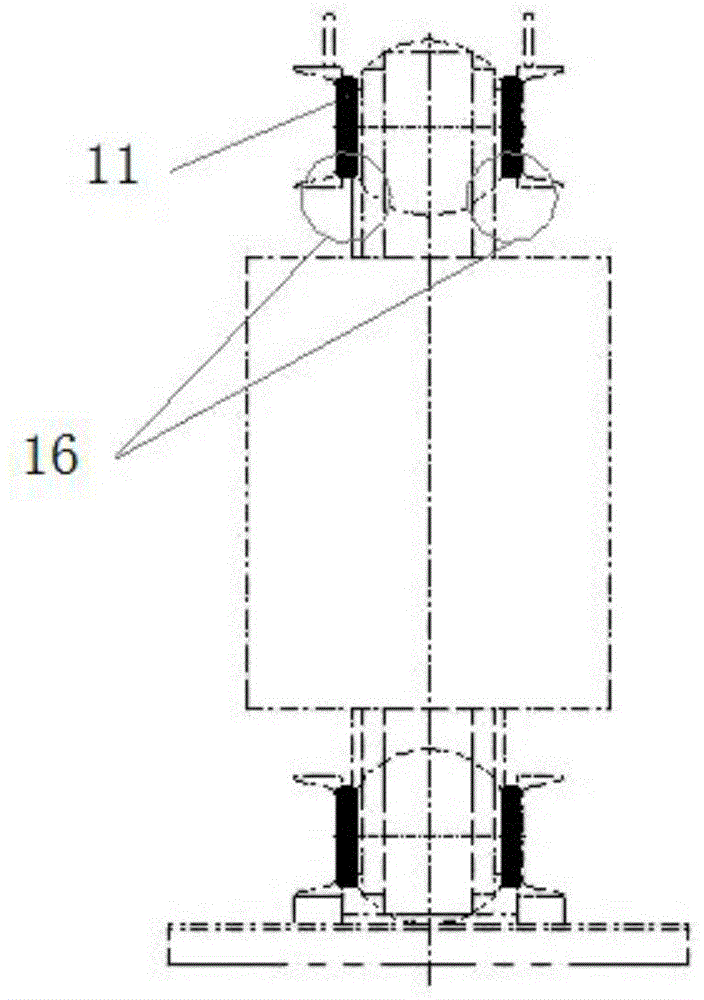
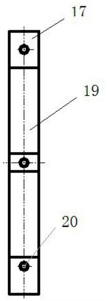
[0017] A dry-type transformer clamp insulation structure, Figure 3-1 It is a schematic diagram of the insulation assembly structure of the clip of the present invention; Figure 3-2 It is a schematic side view of the clamp insulation assembly structure of the present invention; Pic 4-1 It is a schematic diagram of clamp insulation in the present invention; Figure 4-2 It is a schematic side view of the clip insulation in the present invention. In the figure, 1-clamp insulation, 2-upper clamp, 3-core, 4-coil, 5-lower clamp, 6-heat accumulation area, 7-web, 8-support plate, 9-cushion pad, 10-assembly hole, 30-radiating air duct. The structure includes a clamp insulation 1, an upper clamp 2 and a lower clamp 5, the clamp insulation is arranged on the upper clamp and the lower clamp, and the clamp insulation includes a web 7, a support plate 8 and a buffer pad 9, a set The buffer pad and the support plate are parallelogram structures that are compatible with each other, and ...


PUM


Abstract

The invention discloses a clamp insulating structure of a dry-type transformer. The structure comprises clamp insulating parts, an upper clamp and a lower clamp, wherein the clamp insulating parts are arranged on the upper clamp and the lower clamp. Each clamp insulating part comprises a web plate, a support plate and buffer pads, wherein the buffer pads and the support plate are of parallelogram structures which are matched, the buffer pads adhere to the support plate, the set of buffer pads and the support plate adhere to the web plate in a spaced mode, and the web plate is fixed to the upper clamp and the lower clamp. Due to the fact that a heat radiation air channel is formed between the upper clamp and an iron core, heat in an original heat accumulation area is effectively released, and temperature rise of the transformer is reduced. A convection air channel between the lower clamp and the iron core enables air to enter the low portion of a coil smoothly, so that air convection is formed effectively and heat dissipation of the coil is guaranteed. The buffer pads and the support plates are small, and therefore sufficient utilization of materials is facilitated and raw materials are saved greatly.

Description

technical field [0001] The invention belongs to the field of transformer manufacturing and relates to a clip insulation structure of a dry-type transformer. Background technique [0002] The function of transformer clip insulation is the insulation between the iron core and the upper and lower clips to ensure that the iron core is grounded at one point. The clip insulation of the dry-type transformer also plays the role of sound absorption and noise reduction. Picture 1-1 It is a schematic diagram of the traditional clamp insulation assembly structure; Figure 1-2 Schematic diagram of the side view of the traditional clamp insulation assembly structure; diagram 2-1 It is a schematic diagram of the clamp insulation of the traditional structure; Figure 2-2 It is a schematic diagram of the side view of the clamp insulation of the traditional structure. In the figure, 11-clamp insulation, 12-upper clamp, 13-core, 14-coil, 15-lower clamp, 16-heat accumulation area, 17-web, 1...

Claims


Application Information

Patent Timeline
IPC IPC(8): H01F27/26H01F41/02
Inventor 李云孙国平邹遵武
Owner ZHENJIANG TIANLI TRANSFORMER
Why Eureka
Try Eureka