
Microwave induction LED lamp

A technology of microwave induction and LED lamps, which is applied to the layout of electric lamp circuits, cooling/heating devices of lighting devices, lighting and heating equipment, etc., can solve the problems of high malfunction rate, sensitive temperature change, and great influence of sensors, etc., to achieve Small size, energy saving and long service life

Active Publication Date: 2014-11-19
深圳老玩童网络有限公司
View PDF6 Cites 6 Cited by
  • Summary
  • Abstract
  • Description
  • Claims
  • Application Information

AI Technical Summary

Problems solved by technology

[0002] In places where on-demand lighting is required, such as office buildings, residential buildings, and workshop stairs, elevator rooms, toilets, corridors, basements, and car awnings, infrared induction and sound automatic induction lights are widely used, but both will be affected by external factors. Sensitive to changes in air ambient temperature, air flow has a great impact on the sensor, and when used outdoors, the misoperation rate is high; the sound-activated sensor light uses sound to generate signals, and any interference noise that meets the trigger requirements will cause misoperation
[0003] Nowadays, LED technology is very developed, and LED is also used in the above-mentioned automatic lighting occasions. The existing technology does not give full play to the advantages of LED stepless dimming. Generally, there are only a few LED light states, such as full bright, half bright or extinguished.

Method used


Image

  • Microwave induction LED lamp
  • Microwave induction LED lamp
  • Microwave induction LED lamp

Examples


Embodiment Construction

[0036] In order to make the object, technical solution and advantages of the present invention clearer, the present invention will be further described in detail below in conjunction with the accompanying drawings and embodiments. It should be understood that the specific embodiments described here are only used to explain the present invention, not to limit the present invention.

[0037] On the contrary, the invention covers any alternatives, modifications, equivalent methods and schemes within the spirit and scope of the invention as defined by the claims. Further, in order to make the public have a better understanding of the present invention, some specific details are described in detail in the detailed description of the present invention below. The present invention can be fully understood by those skilled in the art without the description of these detailed parts.

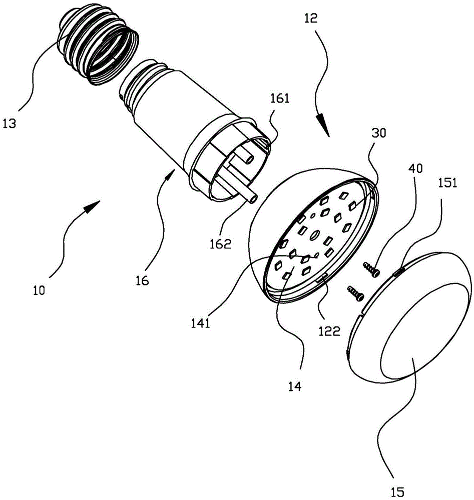
[0038] see Figure 1-Figure 2 The microwave induction LED lamp includes a lamp holder 13, an LED lamp...


PUM


Abstract

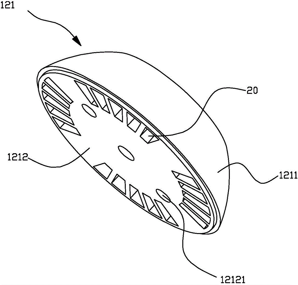
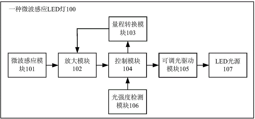
The invention discloses a microwave induction LED lamp which comprises a lamp cap, an LED lamp panel and a lampshade. The lamp cap is in threaded connection with the top of a base. The base is of a hollow cylinder shape, and the tail end of the base is fixedly provided with a heat dissipater. The inner wall of the base is provided with two symmetrical limiting grooves. The inner wall of the base is provided with two hollow fixing columns extending to the tail end of the base. The heat dissipater comprises a heat dissipater shell of a hollow circular truncated cone shape and a plurality of heat-dissipating fins. The heat dissipater shell comprises a heat dissipater outer shell and a heat-dissipating fin substrate. The heat dissipater outer shell is fixedly connected with the heat-dissipating fin substrate. The heat-dissipating fins are uniformly welded to the heat-dissipating fin substrate. The LED lamp further comprises drive circuit boards installed in the limiting grooves. The microwave induction LED lamp is simple in circuit, low in cost, reliable and stable; moreover, the illumination brightness can be automatically adjusted in an electrodeless mode along with the distance between people and the LED lamp, and more comfortable illumination can be provided for people.

Description

technical field [0001] The invention relates to the field of LED lighting, in particular to a microwave-sensing LED lamp capable of sensing human body movement. Background technique [0002] In places where on-demand lighting is required, such as office buildings, residential buildings, and workshop stairs, elevator rooms, toilets, corridors, basements, and car awnings, infrared induction and sound automatic induction lights are widely used, but both will be affected by external factors. Sensitive to changes in air ambient temperature, air flow has a great impact on the sensor, and when used outdoors, the false action rate is high; the sound-activated sensor light uses sound to generate signals, and any interference noise that meets the trigger requirements will cause misoperation. [0003] Nowadays, LED technology is very developed, and LED is also used in the above-mentioned automatic lighting occasions. The existing technology does not give full play to the advantages of ...

Claims


Application Information

Patent Timeline
IPC IPC(8): F21S2/00F21V17/00F21V17/12F21V19/00F21V23/00F21V29/00H05B37/02F21Y101/02
Inventor 胡斌邵李焕崔佳民
Owner 深圳老玩童网络有限公司
Learn More