
Micro power electric equipment rotating and hoisting device

A technology of electric power equipment and lifting devices, which is applied in hoisting devices, portable lifting devices, cranes, etc., can solve the problems of time-consuming and labor-consuming, long lifting and power failure time, high cost, etc., and achieve the effect of improving the safety factor

Inactive Publication Date: 2014-11-19
国网河南唐河县供电公司
View PDF8 Cites 6 Cited by
  • Summary
  • Abstract
  • Description
  • Claims
  • Application Information

AI Technical Summary

Problems solved by technology

First, in electric power construction, there are often problems such as dense equipment structures, dense wiring, etc., and cranes cannot enter and hoist. Generally, human hinges are used for hoisting. The operation of human hinges is complicated and requires the cooperation of multiple people. Not only labor-intensive Large, time-consuming and labor-intensive, long lifting and power outage time, at the same time, there are certain safety risks in the operation; second, even if the crane or other lifting equipment can enter the construction site, it often needs to rely on large-scale power outages to ensure the safety of the construction The safe distance will affect the normal power supply; third, because the rental fee of the lifting equipment is calculated on time, the cost is relatively high
In mountainous areas and areas with poor economic conditions, it is often difficult to install transformers, circuit breakers and other large-scale equipment on the platform. Accident; In CN 201040693Y, a kind of household weight hoist is disclosed, which is characterized in that the frame is composed of vertical frame, horizontal frame, small vertical frame and steel bar slideway, and fixed pulley and movable fixed pulley are respectively arranged on it, One end of the control line is tied to the tether ring, the other end is tied to the control line hook through the fixed pulley and the fixed pulley, one end of the wire rope is tied to the wire rope tie plate, and the other end is fixed through the movable pulley, the movable fixed pulley and the fixed pulley On the winch, pull the control line to move the movable pulley and hook out of the window. After the heavy object is lifted in place, the heavy object will be automatically moved into the balcony or indoor under the action of the fixed pulley and wire rope. In addition, a handle can be installed on the drive shaft to prevent power failure. , but it is not labor-saving enough, and the motor is too large and needs enough electric energy, which is not conducive to field use; a pulley type manhole cover lifting tool is disclosed in 202054546U; it belongs to a lifting tool; it consists of a base part, a supporting part And the lifting part is composed of three parts; the base part includes two parallel base support rods and support rods connected at both ends of the two parallel base support rods
The support part is composed of a support pole with a boss, a rotatable sleeve set on the support pole, a telescopic support rod I and a telescopic support rod II; the lifting part includes a movable pulley, two fixed pulleys and a hand-operated Wire winding device; a hinge is fixed on the movable pulley, and the hinge is connected with a hook for hooking the manhole cover; although it has a good lifting effect, it is relatively laborious, so a micro-power electric equipment rotary lifting device is needed

Method used


Image

  • Micro power electric equipment rotating and hoisting device
  • Micro power electric equipment rotating and hoisting device
  • Micro power electric equipment rotating and hoisting device

Examples


specific Embodiment 1

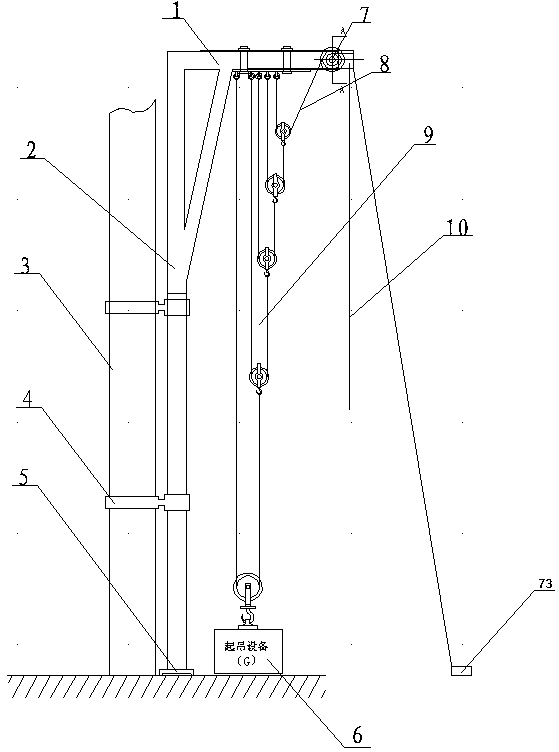
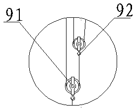
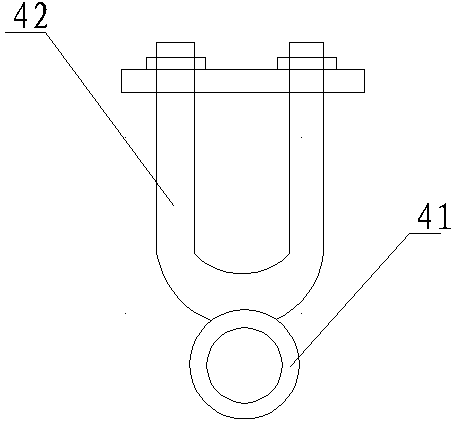
[0022] A rotary lifting device for micro-power electric equipment, comprising a right-angle steel pipe frame, a movable pulley block 9, a rope 8 and a driving mechanism 7, the right-angle steel pipe frame is an inverted L shape composed of an upper rod 1 and a vertical rod 2 fixedly connected, the A hoop 4 is set on the vertical bar 2, a drive mechanism 7 is set on the upper end of the upper bar 1, a movable pulley block 9 is arranged in the middle of the upper bar 1, and one end of the rope 8 is fixed and the other end passes through the movable pulley block 9 to communicate with the drive mechanism 7. Connect; the movable pulley block 9 includes a movable pulley lifting module, the number of the movable pulley lifting modules is five, and the movable pulley lifting modules are arranged side by side in sequence, and one end of the rope of the previous movable pulley lifting module is lifted with the movable pulley 91 in the latter movable pulley lifting module The hook 92 is c...

Embodiment 2

[0025] A rotary lifting device for micro-power electric equipment, comprising a right-angle steel pipe frame, a movable pulley block 9, a rope 8 and a driving mechanism 7, the right-angle steel pipe frame is an inverted L shape composed of an upper rod 1 and a vertical rod 2 fixedly connected, the A hoop 4 is set on the vertical bar 2, a drive mechanism 7 is set on the upper end of the upper bar 1, a movable pulley block 9 is arranged in the middle of the upper bar 1, and one end of the rope 8 is fixed and the other end passes through the movable pulley block 9 to communicate with the drive mechanism 7. Connect; the movable pulley block 9 includes a movable pulley lifting module, the number of the movable pulley lifting modules is five, and the movable pulley lifting modules are arranged side by side in sequence, and one end of the rope of the previous movable pulley lifting module is lifted with the movable pulley 91 in the latter movable pulley lifting module The hook 92 is c...

Embodiment 3

[0030]A rotary lifting device for micro-power electric equipment, comprising a right-angle steel pipe frame, a movable pulley block 9, a rope 8 and a driving mechanism 7, the right-angle steel pipe frame is an inverted L shape composed of an upper rod 1 and a vertical rod 2 fixedly connected, the A hoop 4 is set on the vertical bar 2, a drive mechanism 7 is set on the upper end of the upper bar 1, a movable pulley block 9 is arranged in the middle of the upper bar 1, and one end of the rope 8 is fixed and the other end passes through the movable pulley block 9 to communicate with the drive mechanism 7. Connect; the movable pulley block 9 includes a movable pulley lifting module, the number of the movable pulley lifting modules is five, and the movable pulley lifting modules are arranged side by side in sequence, and one end of the rope of the previous movable pulley lifting module is lifted with the movable pulley 91 in the latter movable pulley lifting module The hook 92 is co...


PUM


Abstract

The invention discloses a micro power electric equipment rotating and hoisting device comprising a right-angle steel pipe frame, a moving pulley group, a rope and a drive mechanism. The right-angle steel pipe frame is composed of an upper rod and a vertical rod which are connected fixedly and is in an inverted L shape, the vertical rod is provided with a fastener, the upper portion of the tail end of the upper rod is provided with the drive mechanism, the middle of the upper rod is provided with the moving pulley group, one end of the rod is fixed to the upper rod, and the other end penetrates the moving pulley group to connect to the drive mechanism; the moving pulley group comprises five pulley lifting modules which are arranged in rows sequentially, one end of the rope of the last moving pulley lifting module is connected to a moving pulley lifting hook of the next moving pulley lifting module, and the tail end of the rope is connected to the drive mechanism. The device is small in size, is capable of being adaptive to the narrow operation environment, is capable of hoisting heavy objects on the condition that large-scale hoisting equipment is not easy to adopt and is worthy of promotion and application.

Description

technical field [0001] The invention belongs to the technical field of labor-saving lifting, and in particular relates to a rotary lifting device for micro-power electric equipment. technical background [0002] During the installation, replacement or overhaul of the power grid, lifting power equipment is often encountered. First, in electric power construction, there are often problems such as dense equipment structures, dense wiring, etc., and cranes cannot enter and hoist. Generally, human hinges are used for hoisting. The operation of human hinges is complicated and requires the cooperation of multiple people. Not only labor-intensive Large, time-consuming and labor-intensive, long lifting and power outage time, at the same time, there are certain safety risks in the operation; second, even if the crane or other lifting equipment can enter the construction site, it often needs to rely on large-scale power outages to ensure the safety of the construction The safe distanc...

Claims


Application Information

Patent Timeline
IPC IPC(8): B66D3/08B66C25/00
Inventor 陈慎张琼
Owner 国网河南唐河县供电公司
Learn More