
Material poking mechanism used for packing machine

A technology of feeding mechanism and packaging machine, applied in packaging and other directions, can solve the problems of unsatisfactory effect and slow pushing speed of cylinder

Inactive Publication Date: 2014-11-19
SUZHOU SHENGBAIWEI PACKAGE EQUIP
View PDF7 Cites 2 Cited by
  • Summary
  • Abstract
  • Description
  • Claims
  • Application Information

AI Technical Summary

Problems solved by technology

[0002] At present, most of the feeding mechanisms of packaging machines in the same industry on the market use devices such as cylinder pushers or motor-driven connecting rods for feeding and sorting. Since the feeding mechanism is located on the front-end feeding conveyor line, its speed needs to be It matches the conveying speed of the packaging machine. According to the different requirements of the packaging machine, the feeding speed may need to be greater than the speed of the packaging machine, and the speed of the cylinder pushing the material is too slow. The ordinary motor drives the connecting rod to push the material, and the connecting rod rotates at the end Sometimes the finished products will be messed up again, and the desired effect will not be achieved.

Method used


Image

  • Material poking mechanism used for packing machine
  • Material poking mechanism used for packing machine
  • Material poking mechanism used for packing machine

Examples


Embodiment Construction

[0018] The present invention will be described in detail below with reference to the accompanying drawings and in combination with embodiments.

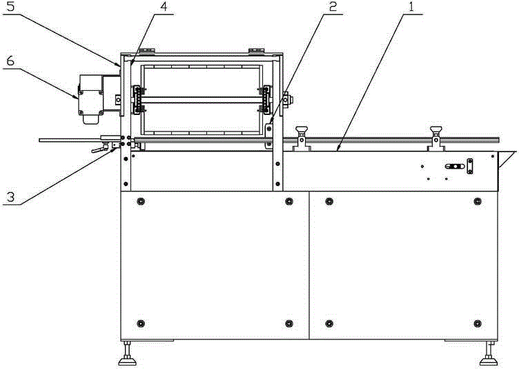
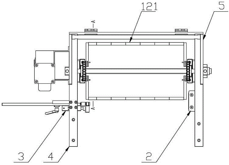
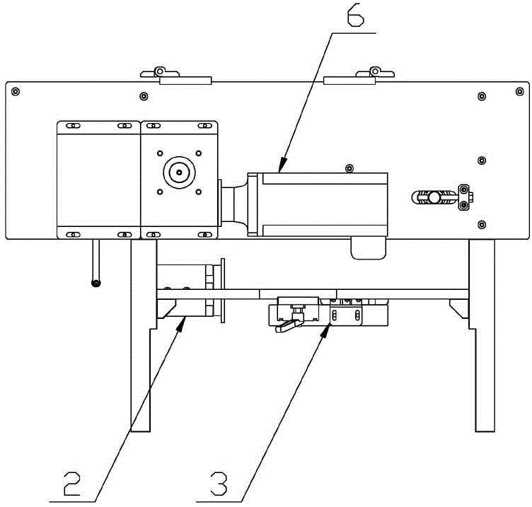
[0019] refer to Figure 1 to Figure 5 As shown, a material shifting mechanism for a packaging machine includes a lower conveying line 1 and four uprights 4, the uprights 4 are installed and fixed on the frame of the lower conveying line 1, side plates 5 are mounted on the left and right sides of the uprights 4, And the driving motor 6, driving shaft 7, and driven tensioning shaft 8 installed on the installation side plate 5, the rotating shaft of the driving motor 6 is connected and drives the driving shaft 7 through a transmission mechanism, and the driven tensioning shaft 8 is mounted on the installation side plate The position on the 5 is adjustable, and the distance from the driving shaft 7 is adjusted as required. A pair of driving sprockets 9 and a pair of driven sprockets 10 are respectively installed on the driving shaft 7 an...


PUM


Abstract

The invention discloses a material poking mechanism used for a packing machine. The material poking mechanism used for the packing machine comprises a lower conveying line, four stand columns, a left installation side board, a right installation side board, a drive motor, a drive shaft and a driven tensioning shaft, wherein the left installation side board and the right installation side board are installed on the side faces of the stand columns, the drive motor, the drive shaft and the driven tensioning shaft are installed on the installation side boards, the drive shaft and the driven tensioning shaft are provided with a pair of drive chain wheels and a pair of driven chain wheels respectively, the drive chain wheels and the driven chain wheels are linked and driven by hollow chains, pin shafts of the hollow chains are provided with connecting rod material poking assemblies, and the connecting rod material poking assemblies are connected through two movable pin shafts on the hollow chains. Stress resistance of the material poking assemblies can be improved, and it is avoided that the material poking assemblies bear resistance and deform in the material poking process. Meanwhile, the multiple sets of connecting rod material poking assemblies can be arranged at equal intervals to improve the material poking efficiency, material poking rods in the connecting rod material poking assemblies are provided with cylindrical rollers which can rotate by themselves in the material poking process, and products are prevented from being poked disorderly.

Description

technical field [0001] The invention belongs to the field of packaging machines, and in particular relates to a material shifting mechanism for a packaging machine. Background technique [0002] At present, most of the feeding mechanisms of packaging machines in the same industry on the market use devices such as cylinder pushers or motor-driven connecting rods for feeding and sorting. Since the feeding mechanism is located on the front-end feeding conveyor line, its speed needs to be It matches the conveying speed of the packaging machine. According to the different requirements of the packaging machine, the feeding speed may need to be greater than the speed of the packaging machine, and the speed of the cylinder pushing the material is too slow. The ordinary motor drives the connecting rod to push the material, and the connecting rod rotates at the end Sometimes the sorted products will be messed up again, and the desired effect will not be achieved. Contents of the inv...

Claims


Application Information

Patent Timeline
IPC IPC(8): B65B35/44
Inventor 张太元
Owner SUZHOU SHENGBAIWEI PACKAGE EQUIP
Learn More