
Winding tool for windings

A wire winding and tooling technology, applied in coil manufacturing, electrical components, inductor/transformer/magnet manufacturing, etc., can solve problems such as uneven winding

Inactive Publication Date: 2014-11-12
STATE GRID CORP OF CHINA +1
View PDF6 Cites 3 Cited by
  • Summary
  • Abstract
  • Description
  • Claims
  • Application Information

AI Technical Summary

Problems solved by technology

[0003] The purpose of the present invention is to provide a winding tooling for winding, which is used to solve the problem of uneven winding caused by manual winding of existing windings

Method used


Image

  • Winding tool for windings
  • Winding tool for windings
  • Winding tool for windings

Examples


Embodiment Construction

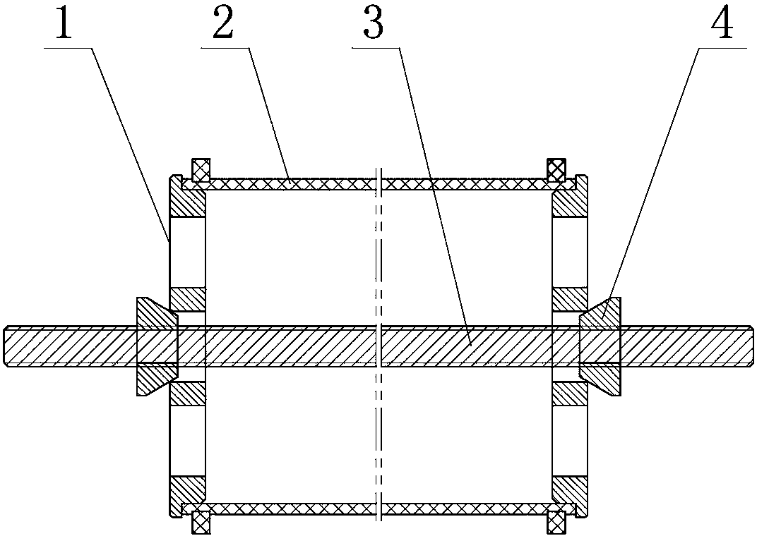
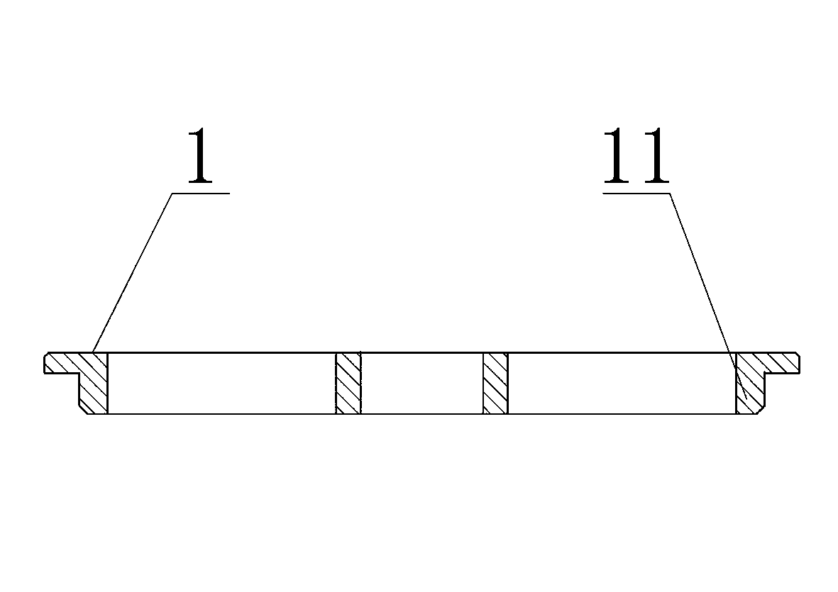
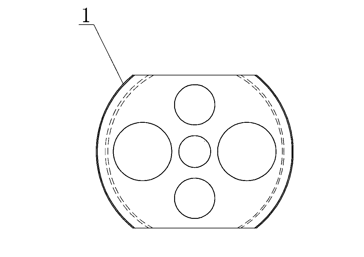
[0011] The embodiment of winding frock of the present invention: as Figure 1-3 As shown, the screw rod 3 is included, and the screw rod 3 is covered with two splints 1 arranged at intervals from left to right. Nut 4, lock nut 4 is a conical nut, and its outer peripheral surface is a conical surface, and the small diameter ends of the two lock nuts 4 are arranged oppositely, and the small diameter ends of the lock nut 4 go deep into the gap between the screw rod 3 and the corresponding clamping plate at the same time In the gap; when the conical surface of the lock nut 4 and the inner hole of the corresponding splint are pressed together, the coaxiality of the splint 1 and the screw rod 3 can be automatically realized, and the two lock nuts 4 can be screwed in the opposite direction, which can A force of relative movement along the axial direction of the screw rod 3 is applied to the two splints 1 . In this embodiment, the function of the two splints 1 is to clamp the insulat...


PUM


Abstract

The invention discloses a winding tool for windings. The winding tool comprises a screw and two clamping plates which movably sleeve the screw in a penetrated manner and are used for clamping an insulating cylinder arranged on the screw in a sleeving manner, wherein lock nuts which apply opposite moving acting forces to the two clamping plates to clamp the insulating cylinder are spirally screwed and mounted in positions, which are located on outer sides of the two clamping plates, of the screw; supporting parts for radially supporting the insulating cylinder to ensure that the insulating cylinder and the screw are coaxial are arranged on opposite plate surfaces of the two clamping plates in a bulging manner respectively. The whole tool and the insulating cylinder adopt an integrated structure, the integrated structure is installed on a winding machine by the aid of the screw, and the winding machine drives the screw to rotate together with the insulating cylinder, so that mechanical winding on the insulating cylinder is realized, the labor intensity of workers is reduced, the winding efficiency is high, and the winding quality is guaranteed; the whole tool also has the advantages of simple structure and convenience in mounting and dismounting.

Description

technical field [0001] The invention relates to a wire winding tool which can be used for winding the secondary winding of a voltage transformer. Background technique [0002] The winding of the secondary winding of the traditional voltage transformer is manually wound, that is, the worker uses the enameled wire of the specified type to manually wind the specified number of turns (20-100 turns) on the insulating cylinder of the secondary winding. Manual operation leads to low winding efficiency and high labor intensity, and more importantly, it cannot guarantee the uniformity of winding. Contents of the invention [0003] The object of the present invention is to provide a winding tool for winding, which is used to solve the problem of uneven winding caused by manual winding of existing windings. [0004] The present invention adopts the following technical scheme: a winding tooling for winding, including a screw rod and two splints that are movably threaded on the screw ...

Claims


Application Information

Patent Timeline
Patent Type & Authority Applications(China)
IPC IPC(8): H01F41/06H01F41/098
Inventor 李阳
Owner STATE GRID CORP OF CHINA
Learn More