
Multi-stage aeration device

An aeration device and aeration technology, applied in transportation and packaging, mixers, mixing methods, etc., can solve problems such as reducing system efficiency

Inactive Publication Date: 2016-08-24
SEAIR INC
View PDF4 Cites 0 Cited by
  • Summary
  • Abstract
  • Description
  • Claims
  • Application Information

AI Technical Summary

Problems solved by technology

This reduces the efficiency of the system

Method used


Image

  • Multi-stage aeration device
  • Multi-stage aeration device
  • Multi-stage aeration device

Examples


Embodiment Construction

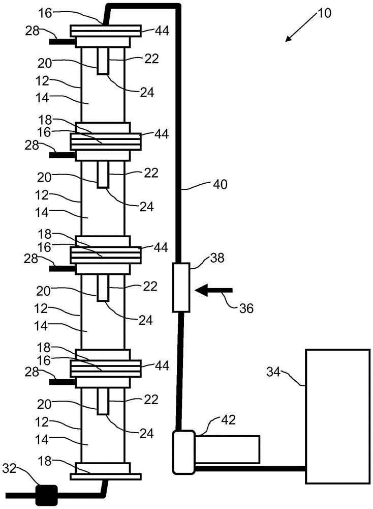
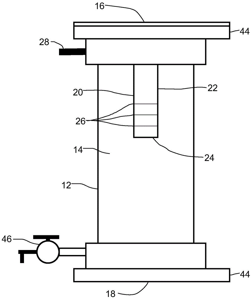
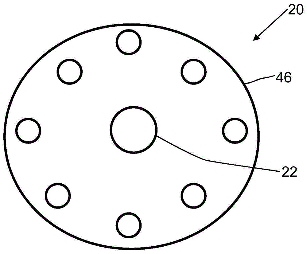
[0023] will now refer to Figures 1 to 4 A multi-stage aeration device, generally designated by reference numeral 10, is described.

[0024] Structure and relationship of components:

[0025] refer to figure 1 and 2 , the multistage aeration device 10 includes at least two vertically oriented aeration modules 12 . Each aeration module 12 defines a vertically extending aeration chamber 14 having a top inlet 16 and a bottom outlet 18 . The bottom outlet 18 of each aeration module 12 feeds liquid into the top inlet 16 of the one below that aeration module. The first aeration module 12 receives a gas / liquid mixture from gas and liquid sources. Gas may be injected using, for example, a pressurized source of gas or a venturi. As shown, there is a source of liquid 34 and a source of gas 36 mixed with a venturi 38 . Liquid is driven through venturi 38 and fluid line 40 using pump 42 . Liquid and gas flows may be referred to as fluid flows. As the fluid flows through the devic...


PUM


Abstract

A multi-stage aeration device comprising at least two vertically oriented aeration modules is provided. Each aeration module defines a vertically extending aeration chamber with a top inlet and a bottom outlet. The bottom outlet of each aeration module feeds a fluid stream including liquid and gas into the top inlet of the aeration module below that aeration module. Each aeration module has an aeration head connected to the top inlet such that the fluid flow entering the aeration chamber through the top inlet must pass through the aeration head, which utilizes all the The gas in the fluid stream aerates the liquid.

Description

technical field [0001] The present application relates to an aeration device having a series of gas injection and reaction zones therein. Background technique [0002] Aeration systems are used in many different applications, including wastewater treatment. The use of aeration towers in series is inefficient and space consuming, and it is difficult to equalize the back pressure within the system. If a single column is used and the fluid is recirculated through the tank, the treated fluid with microbubbles passing through the injector and pump breaks down and forms larger bubbles. This reduces the efficiency of the system. Contents of the invention [0003] A multi-stage aeration device is provided, comprising at least two vertically oriented aeration modules, each aeration module defining a vertically extending aeration chamber having a top inlet and a bottom outlet, each aeration module The bottom outlet feeds the fluid flow of liquid and gas into the top inlet of the ...

Claims


Application Information

Patent Timeline
Patent Type & Authority Patents(China)
IPC IPC(8): B01F3/04B01F5/00C02F1/74
CPCB01F23/2322B01F23/2323B01F23/23412B01F25/3121B01F33/821B01F33/811C02F1/74B01F23/23B01F25/31B01F23/2319B01F25/312B01F2101/305
Inventor K·格林T·韦布
Owner SEAIR INC
Learn More