
Lower door interlocking device of two-hole operating mechanism

An operating mechanism and door interlocking technology, which is applied in the direction of vertical pulling and isolating switch devices, can solve the problems of complex interlocking mechanism settings, high manufacturing costs, inconvenient installation, etc., and achieves simple, safe and reliable installation and implementation methods. Production cost, ingenious effect of structural design

Active Publication Date: 2014-11-05
JIANGSU DAQO CHANGJIANG ELECTRICAL
View PDF5 Cites 3 Cited by
  • Summary
  • Abstract
  • Description
  • Claims
  • Application Information

AI Technical Summary

Problems solved by technology

[0002] The operation process of the existing double-hole switch operating mechanism is divided into three working positions, which are closing, opening and grounding. However, because the structure of the double-hole switch operating mechanism is single and there is no interlocking mechanism, the operator must It is easy to skip the opening position from the grounding position and directly operate to the closing position, or skip the opening position from the closing position and directly operate to the grounding position, making its operation extremely unreliable. This misoperation often brings some potential safety hazards , it is easy to cause equipment damage or even work-related injuries, and there are some interlocking mechanisms in the prior art, but the setting of these interlocking mechanisms is relatively complicated, the production cost is high, and the installation is inconvenient. application

Method used


Image

  • Lower door interlocking device of two-hole operating mechanism
  • Lower door interlocking device of two-hole operating mechanism
  • Lower door interlocking device of two-hole operating mechanism

Examples


Embodiment Construction

[0013] The present invention is described in further detail now in conjunction with accompanying drawing. These drawings are all simplified schematic diagrams, which only illustrate the basic structure of the present invention in a schematic manner, so they only show the configurations related to the present invention.

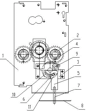
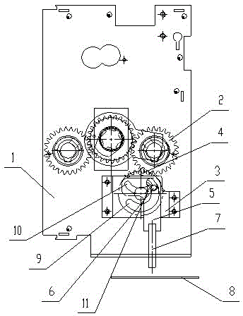
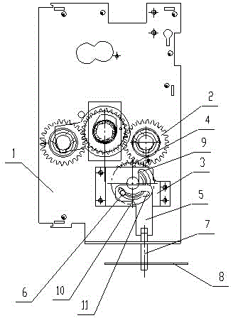
[0014] Such as Figure 1-3 As shown, a lower door interlocking device of a double-hole operating mechanism includes a main body 1, a lower door 8 and a driving gear 2 arranged on the main body 1, the lower door 8 is correspondingly arranged under the main body 1, and the driving gear 2. There is an interlocking assembly below. The interlocking assembly includes a transmission gear 4, a support plate 3, a positioning pin 6 and an interlocking slide plate 5. The support plate 3 is fixed on the main body 1, and the support plate 3 is provided with Arc-shaped bar-shaped hole 9, the transmission gear 4 is arranged between the support plate 3 and the main body 1, t...


PUM


Abstract

The invention relates to a lower door interlocking device of a two-hole operating mechanism. The lower door interlocking device comprises a main body, a lower door and a driving gear arranged on the main body, wherein the lower door is correspondingly arranged below the main body; an interlocking assembly is arranged below the driving gear, and comprises a transmission gear, a support plate, a locating pin and an interlocking slide plate; the support plate is fixed on the main body; an arc strip-type hole is formed in the support plate; the transmission gear is engaged with the driving gear; the locating pin is arranged on one side of the center of the transmission gear, and is perpendicular to the transmission gear; a travelling strip-type hole which can be matched with the locating pin to allow the interlocking slide plate to move up and down is formed in the interlocking slide plate; and a bolt is arranged at the lower part of the interlocking slide plate. According to the lower door interlocking device of the two-hole operating mechanism, the transmission gear drives the locating pin to form an eccentric wheel, and rotation of the transmission gear drives the interlocking slide plate to move up and down, so that the lower door interlocking device is ingenious in overall structure design, simple to mount and realize, low in manufacturing cost, safe and reliable, and is suitable for popularization and application.

Description

technical field [0001] The invention relates to the field of medium and high voltage power transmission and distribution technical equipment, in particular to a lower door interlocking device of a double hole operating mechanism. Background technique [0002] The operation process of the existing double-hole switch operating mechanism is divided into three working positions, which are closing, opening and grounding. However, because the structure of the double-hole switch operating mechanism is single and there is no interlocking mechanism, the operator must It is easy to skip the opening position from the grounding position and directly operate to the closing position, or skip the opening position from the closing position and directly operate to the grounding position, making its operation extremely unreliable. This misoperation often brings some potential safety hazards , it is easy to cause equipment damage or even work-related injuries, and there are some interlocking m...

Claims


Application Information

Patent Timeline
IPC IPC(8): H02B11/18
Inventor 高明春徐忠秋仇婷吴其乐
Owner JIANGSU DAQO CHANGJIANG ELECTRICAL
Learn More