
Detection device and method for residual current of photovoltaic array

A photovoltaic array, residual current technology, applied in measuring devices, measuring current/voltage, measuring electricity, etc., can solve problems such as hidden dangers, personal and property injury, shock and death that cannot be completely eliminated

Inactive Publication Date: 2014-11-05
THE 41ST INST OF CHINA ELECTRONICS TECH GRP
View PDF7 Cites 7 Cited by
  • Summary
  • Abstract
  • Description
  • Claims
  • Application Information

AI Technical Summary

Problems solved by technology

Although the improved inverter topology circuit structure that can suppress the leakage current is used, it has its limitations and cannot completely eliminate its hidden dangers.
If the leakage current cannot be accurately detected, it may lead to electric shock accidents for inverter operators, and severe cases may lead to shock and death, causing great harm to personal property

Method used


Image

  • Detection device and method for residual current of photovoltaic array
  • Detection device and method for residual current of photovoltaic array
  • Detection device and method for residual current of photovoltaic array

Examples


Embodiment Construction

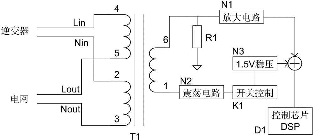
[0023] like figure 1 shown. A photovoltaic array residual current detection device, comprising a leakage detection transformer T1, a DSP control chip D1, an active filter amplifier circuit N1, a 1.5V voltage stabilizing circuit N3, an oscillation circuit N2, a switch control circuit K1, and a leakage detection transformer T1 There are two primary windings on the input side, and one secondary winding on the output side. The two ends 4 and 5 of one of the primary windings on the input side of the leakage detection transformer T1 are respectively connected to the live wire and the AC output of the grid-connected inverter in the photovoltaic array. The live wire of the power grid, the input side of the leakage detection transformer T1, and the two ends 2 and 3 of the primary winding are respectively connected to the neutral line of the output AC of the grid-connected inverter in the photovoltaic array, the neutral line of the power grid, and the output side of the leakage detecti...


PUM


Abstract

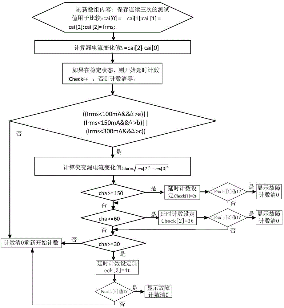
The invention discloses a detection device and method for residual current of a photovoltaic array. The device includes an electricity leakage detection mutual inductor, a DSP control chip, an active filtering amplification circuit, a 1.5V voltage stabilizing circuit, an oscillation circuit, and a switch control circuit. The method obtains the value of a leakage current I through formula computing and judges a continuous leakage current and an abrupt-change leakage current according to the leakage current I. The detection device and method have the characteristics of real-time detection and capable of effectively detecting the leakage current of the photovoltaic array.

Description

technical field [0001] The invention relates to the field of current detection, in particular to a photovoltaic array residual current detection device and method. Background technique [0002] Energy is the most fundamental driving force for social development and economic growth, and the basis for human survival. Human development and energy utilization are closely linked. Fossil energy sources such as coal, oil, and natural gas support the development of human society, but with the large-scale exploitation of these energy sources, the resources are increasingly depleted, and the environment continues to deteriorate, and the contradiction between energy supply and demand is becoming more and more prominent. As a clean and renewable energy source, solar energy has broad application prospects, and grid-connected photovoltaic power generation systems will become a trend. In the photovoltaic grid-connected power generation system, the key device for energy conversion is the g...

Claims


Application Information

Patent Timeline
IPC IPC(8): G01R19/00G01R19/02G01R31/02
Inventor 童树卫陈林贵余志勇钱彬邓允长孙松源
Owner THE 41ST INST OF CHINA ELECTRONICS TECH GRP
Learn More