Eureka AIR delivers breakthrough ideas for toughest innovation challenges, trusted by R&D personnel around the world.

Electromagnetic vapor-plating device

An electromagnetic and evaporation technology, applied in the direction of vacuum evaporation plating, circuits, electrical components, etc., can solve the problems of inability to control the magnetic strength of the magnet, sagging of the shadow mask, and color mixing, so as to improve product yield and avoid color mixing. Effect

Inactive Publication Date: 2014-11-05
EVERDISPLAY OPTRONICS (SHANGHAI) CO LTD
View PDF5 Cites 19 Cited by
  • Summary
  • Abstract
  • Description
  • Claims
  • Application Information

AI Technical Summary

Problems solved by technology

[0007] Among them, the electromagnets of the vapor deposition equipment disclosed in this patent document are distributed in strips, and the magnetic strength of the magnet at the center of the vapor deposition device cannot be controlled. During the vapor deposition process, since the shadow mask deposits more organic matter, This leads to the sagging of the shadow mask at the center, resulting in the problem of color mixing during the coating process, which affects the product yield; at the same time, this technical solution cannot monitor and control the magnetic strength of the electromagnet in real time, thereby meeting the needs of different processes , so the invention has certain limitations in practical application

Method used


Image

  • Electromagnetic vapor-plating device
  • Electromagnetic vapor-plating device
  • Electromagnetic vapor-plating device

Examples


Embodiment 1

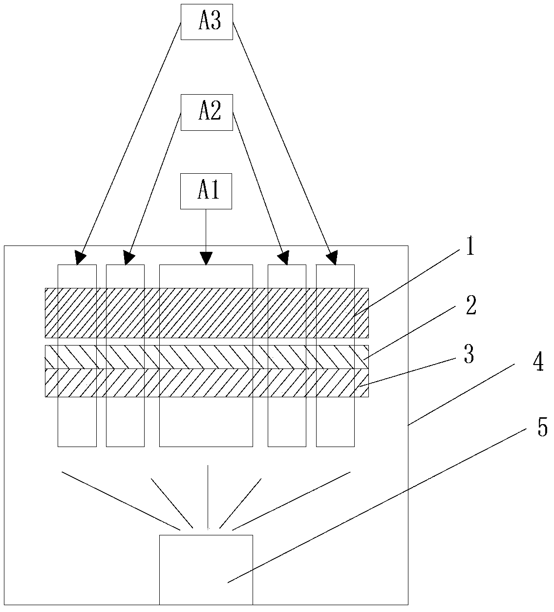
[0028] image 3 The side view of a kind of thermal evaporation device provided for the present invention, as image 3 As shown, the coating control device includes a main reaction chamber 4, the bottom of the main reaction chamber 4 is provided with a film-forming material evaporation source 5, and the top of the evaporation source 5 is sequentially provided with metal shields from bottom to top. Cover 3, hard substrate 2 and clamping frame 1; preferably, the hard substrate 2 is a glass substrate.

[0029] In addition, a plurality of electromagnet units are placed on the clamping frame 1 to attract the metal mask to the lower surface of the hard substrate 2 , and the evaporation source 5 sprays an organic gas source upward to coat the surface of the hard substrate 2 .

[0030] Among them, the plurality of electromagnet units arranged on the clamping frame 1 form the first electromagnetic area A1, the second electromagnetic area A2, the third electromagnetic area A3..., and so...

Embodiment 2

[0034] Preferably, the electromagnetic evaporation device in the present invention also includes a programmable control device and a sensor, the programmable control device is electrically connected with each electromagnet unit, to control the magnetic polarity and magnetic intensity of each electromagnet unit, and the sensor It is also electrically connected with the programmable control device (such as PLC, Programmable Logic Controller programmable control device).

[0035] Figure 5It is a side view of a partial structure of an electromagnetic evaporation device of the present invention; as Figure 5 As shown, a hard substrate 2 is provided between the metal mask 3 and the clamping frame 1, and a sensor 6 is provided above each electromagnetic region formed after the electromagnetic unit fixed on the clamping frame 1 is energized, and the The sensor 6 is a magnetic sensor, which is used to monitor the magnetic force intensity of each electromagnet unit in the electromagne...


PUM


Abstract

The present disclosure discloses an electromagnetic vapor deposition apparatus comprising a plurality of electromagnets which form a plurality of electromagnetic regions when electronic current passes through. A programmable control equipment is electronically connected to each magnet unit to control magnetic polarity and magnetic intensity of each magnet unit. The programmable control equipment can adjust the magnetic intensity of each of the plurality of electromagnetic regions to adsorb the metal mask tightly. Meanwhile, the problem of colors mixing is overcome.

Description

technical field [0001] The present invention relates to an OLED vapor deposition device, to be precise, specifically relates to an electromagnetic vapor deposition device. Background technique [0002] OLED stands for Organic Light-Emitting Diode (Organic Light-Emitting Diode), also known as Organic Electroluminesence Display (OELD). OLED has the characteristics of self-illumination. It adopts a very thin organic material coating and a hard substrate process. When the current passes through, the organic material will emit light. Moreover, the OLED display screen has a large viewing angle and can significantly save power. It has been widely used. use. With the increasing demand for OLEDs, the requirements for OLED technology are getting higher and higher. In OLED technology, packaging upward film-forming technology is a very important and key technology, which directly affects the quality and quality of OLED products. In terms of manufacturing cost, the traditional technolo...

Claims


Application Information

Patent Timeline
Patent Type & Authority Applications(China)
IPC IPC(8): C23C14/24C23C14/12
CPCH01L51/56C23C14/042
Inventor 李嘉宸黃添旺
Owner EVERDISPLAY OPTRONICS (SHANGHAI) CO LTD
Why Eureka
Eureka Blog
Learn More