
Magnetic nut and universal permanent magnet transmission device

A transmission device and nut technology, which is used in transportation and packaging, conveyors, non-mechanical conveyors, etc., can solve the problem of short transmission distances of sliding screws and ball screws, no long-distance continuous curve transmission, and high technical complexity. It can achieve the effect of strong dynamic adaptability, uniform and stable transmission force without fluctuation, and high technical complexity.

Inactive Publication Date: 2014-11-05
DALIAN WHIM SCI & TECH LTD CO
View PDF9 Cites 9 Cited by
  • Summary
  • Abstract
  • Description
  • Claims
  • Application Information

AI Technical Summary

Problems solved by technology

Even if the local section of the production line is all straight, the length of its continuous transmission will greatly exceed the maximum processing length range of the screw. Since the sliding screw and ball screw drive can only be driven on the effective part of the screw, the sliding screw The transmission distance with the ball screw is very short or the length is limited, so it cannot be used for long-distance continuous curve transmission
Although the linear motor technology can be used for long-distance continuous curve transmission, it needs to lay coils or permanent magnets on the entire line, which is costly and technically complex. Moreover, the magnetic circuit of the electromagnetic coil of the linear motor is open, which is harmful to the outside world. The influence of electromagnetic radiation, for the environment without shielding conditions, it will cause radiation influence on the human body, which limits the application conditions

Method used


Image

  • Magnetic nut and universal permanent magnet transmission device
  • Magnetic nut and universal permanent magnet transmission device
  • Magnetic nut and universal permanent magnet transmission device

Examples


Embodiment 1

[0054] Embodiment 1: Linear drive

[0055] Such as Figure 11 with Figure 12 As shown, the universal permanent magnet transmission of the present invention mainly includes a magnetic nut 1, a guide rail 10, a motor 11, a screw 12, a bearing block 13 and a bearing 20, and the screw 12 is in phase with the output shaft of the motor 11. Coupled, fixed on the bearing seat 13, the two ends of the leading screw 12 are supported by the bearing 20 in the bearing seat 13 and can rotate flexibly.

[0056] The screw 12 is made of an external thread structure that protrudes outward around its circumferential surface and is arranged helically along its axis. The screw 12 is single-headed or multi-headed, and the number of heads is preferably an even number. The material of the screw 12 is a guide magnetic material. The cross-section of the threaded portion of the lead screw 12 can be a rectangular cross-section, a trapezoidal cross-section, or other cross-sections.

[0057] Two aforem...

Embodiment 2

[0065] Embodiment 2: curve transmission

[0066] The aforementioned motor 11, leading screw 12, bearing blocks 13 and bearings 21 at both ends constitute a linear transmission unit. When the linear transmission unit is very short, multiple very short linear transmission units can be connected in sequence to form a required curve, and the curve transmission can be realized in the aforementioned manner. Each line segment can be controlled individually to achieve different speeds and actions.

[0067] The invention also provides a synchronous curve transmission structure.

[0068] Such as Figure 13 As shown, when the guide rail 10 is a curve, and when the curve does not require complex motion control, universal joints 18 can be arranged at the two ends of the adjacent lead screw 12 . A plurality of shorter lead screws 12 are connected by universal couplings 18 into continuous line segments to form a continuous curve.

[0069] Such as Figure 14 Shown, adjacent leading screw...


PUM


Abstract

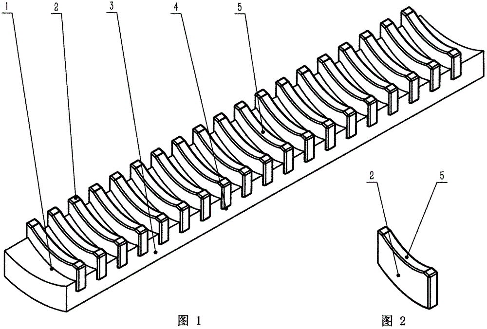
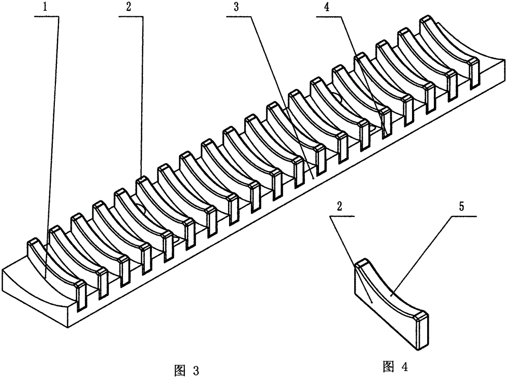
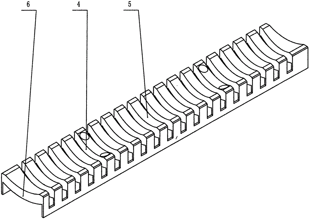
The invention relates to a magnetic nut and a universal permanent magnet transmission device. The universal permanent magnet transmission device comprises a motor, a lead screw, a nut, bearings and a bearing block. The lead screw is directly connected with an output shaft of the motor, the two ends of the lead screw are supported by the bearings, and the bearings are in sliding fit with the bearing block. The universal permanent magnet transmission device is characterized in that a plurality of protruding magnetic poles are distributed on the surface of an outer thread, opposite to the lead screw, of the magnetic nut, each magnetic pole is provided with a circular arc surface, the magnetic poles are distributed according to the directions of the N magnetic pole and the S magnetic pole in a staggered mode, the external diameter of the lead screw and the external diameter of the motor are smaller than the minimum diameter of the magnetic nut, the two ends of the lead screw at the corner are connected with universal couplers, and continuous conveying can be achieved through a conveying trolley via a bent path.

Description

technical field [0001] The invention relates to the technical field of production line transmission and material conveyance, in particular to non-contact magnetic transmission and screw transmission technology, especially for continuous transmission devices used in equipment manufacturing and production lines. Background technique [0002] The transmission of sliding screw and ball screw used in machine tools of equipment manufacturing industry can directly convert circular motion and linear motion, which is simple and efficient, and has been widely used in machine tools and equipment. However, the sliding screw and ball screw can only be used for linear transmission, without any curves and bends. The production line used for parts production and assembly often has straight lines and curves. Even if the local section of the production line is all straight, the length of its continuous transmission will greatly exceed the maximum processing length range of the screw. Since t...

Claims


Application Information

Patent Timeline
Patent Type & Authority Applications(China)
IPC IPC(8): B65G54/02
Inventor 刘忠臣贾振强
Owner DALIAN WHIM SCI & TECH LTD CO
Learn More