
Floating clamping jaw for lathe machining

A floating claw and floating claw seat technology is applied in the field of bearing car processing to achieve the effect of solving the clamping skew and stable clamping.

Inactive Publication Date: 2014-11-05
CHANGSHU CHANGZHOU BEARING
View PDF8 Cites 7 Cited by
  • Summary
  • Abstract
  • Description
  • Claims
  • Application Information

AI Technical Summary

Problems solved by technology

[0005] The technical problem mainly solved by the present invention is: aiming at the deficiencies of the prior art, to provide a floating jaw for lathe processing, which can accurately and reliably position and clamp lathe processing parts, and avoid clamping skew and parts clamping. Deformation, claw wear and other problems, improve clamping accuracy

Method used

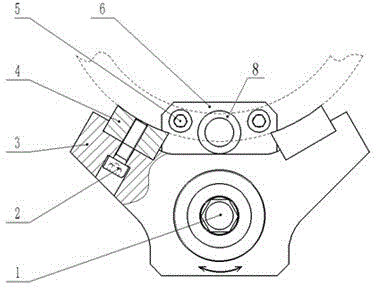
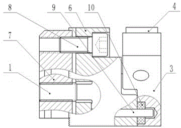

Image

  • Floating clamping jaw for lathe machining
  • Floating clamping jaw for lathe machining

Examples


Embodiment Construction

[0015] The preferred embodiments of the present invention will be described in detail below in conjunction with the accompanying drawings, so that the advantages and features of the present invention can be more easily understood by those skilled in the art, so as to define the protection scope of the present invention more clearly.

[0016] see Figure 1-Figure 2 , the embodiment of the present invention includes:

[0017] A floating jaw for turning, comprising: a floating jaw 3 sequentially connected by a floating jaw screw 1, a floating jaw seat 6 and a floating jaw T-block 7, the floating jaw seat 6 and the floating jaw The T-shaped block 7 is fixed by the clamping screw 8, the floating claw 3 is rotatably limited on the floating claw screw 1, and the working surface of the floating claw 3 is symmetrically fixed by the hexagon socket head screw 2 There are two floating claw pads 4, and the floating claw seat 6 and the floating claw 3 are also connected through a positioni...


PUM


Abstract

The invention discloses a floating clamping jaw for lathe machining. The floating clamping jaw comprises a floating clamping jaw body, a floating clamping jaw base and a floating jaw T-shaped block which are sequentially connected through a floating jaw screw, the floating clamping jaw base and the floating jaw T-shaped block are fixed through a clamping screw, the floating clamping jaw is limited to the floating jaw screw in a rotating mode, the working face of the floating clamping jaw is fixedly provided with a plurality of floating jaw cushion blocks, the floating clamping jaw base is connected with the floating clamping jaw body through a positioning pin, and an elastic deformation body is further arranged between the positioning pin and the floating clamping jaw body in a sleeved mode. By means of the method, parts to be machined through a lathe can be positioned and clamped precisely and reliably, problems of inclined clamping, deformation of part clamping, clamping jaw wear and the like are avoided and clamping accuracy is improved.

Description

technical field [0001] The invention relates to the technical field of bearing turning, in particular to a floating jaw for turning. Background technique [0002] Usually, in various types of lathes, the clamping and positioning device used is a three-jaw chuck. The ordinary three-jaw chuck does not position the axial direction of the part when machining the inner hole of the part, which may cause clamping The axis of the holding part and the axis of the three-jaw chuck are skewed (clamping). [0003] In addition, the three-jaw chuck has been used for a long time. With the wear of the jaws, the center of the three-jaw will deviate from the center of the main shaft of the lathe, which will increase the shape and position tolerance of the processed parts. [0004] Especially when processing thin-walled parts, the three-jaw chuck can only be in three-point contact with the part. Even a slight clamping force will cause the part to produce "round edges". "It's also hard to fix....

Claims


Application Information

Patent Timeline
Patent Type & Authority Applications(China)
IPC IPC(8): B23B31/103
CPCB23B31/103
Inventor 陈胜东张伟
Owner CHANGSHU CHANGZHOU BEARING
Learn More