Screw delivery rack for electric drill

An electric drill and screw technology, applied in the field of screw conveying device, can solve the problems of small scope of application, easy loss and crooked screws, high cost of electric drive, and achieve the effects of changing the heavy and heavy carrying, broad market prospect and simple structure

Active Publication Date: 2019-12-10
孙艳
View PDF9 Cites 0 Cited by
  • Summary
  • Abstract
  • Description
  • Claims
  • Application Information

AI Technical Summary

Problems solved by technology

[0002] Electric drills are widely used to tighten screws. It is very troublesome to transfer screws manually, and the screws are easy to be lost and crooked. In the prior art, the automatic delivery of electric drill screws mostly adopts the method of vacuum pump suction nails, which needs to be equipped with other equipment. It is difficult to carry and operate. Electric drill screws There are also innovations in the delivery, such as the utility model patent "an automatic feeding electric screwdriver" (patent number: 200850151815.X) which adopts the technical solution of connecting the feeding component at the head of the screwdriver with the inclined pneumatic feeding tube; the utility model patent "automatic lock Screw machine" (Patent No.: 2013203296291), which uses two feed tubes to transmit screws with different diameters to multiple vertical piercing holes on the distribution block, and the distribution block moves horizontally with a single penetration hole and When the material guide holes are concentric, the screws with different diameters fall to the material guide holes; although the above technology improves the efficiency, there are still problems such as the inclination of the feeding pipe and the inability to transport long-stem screws, high cost of electric drive, inconvenient operation of equipment, and small scope of application, etc. limitations

Method used


Image

  • Screw delivery rack for electric drill
  • Screw delivery rack for electric drill
  • Screw delivery rack for electric drill

Examples


Embodiment Construction

[0027] The technical solutions of the present invention will be clearly and completely described below in conjunction with the accompanying drawings in the embodiments of the present invention.

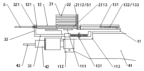
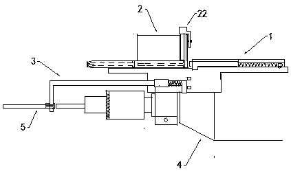
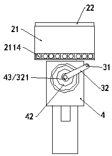
[0028] As shown in the figure, the electric drill screw delivery rack includes a nail pushing mechanism 1 , a nail removing mechanism 2 , and a nail turning mechanism 3 .

[0029] 1. Push nail mechanism.

[0030] Such as Figure 1 to Figure 6 As shown, the push nail mechanism includes a frame plate 11, a through pipe 12, and a push bolt 13. The frame plate 11 is placed flat on the hand-held electric drill 4, and the clip 112 on the bottom surface is enclosed and fixed with the front end of the electric drill body 41. The front end of the frame plate is installed through a Pipe 12 is used to transmit the screw 5, and the middle is a deck 111, which is used for positioning and placing the nail box 21 that can move to both sides. The rear end is equipped with a push bolt 13, which is us...


PUM


Abstract

The invention discloses a screw delivery rack for an electric drill; the screw delivery rack comprises a screw pushing mechanism, a screw discharging mechanism and a screw turning mechanism, wherein the screw pushing mechanism comprises a rack plate, a through pipe and a pushing bolt, the rack plate is levelly arranged at the upper bottom end of the electric drill and fixed with the electric drillmachine body, the through pipe at the front end of the rack plate and the pushing bolt at the rear end of the rack plate are linearly arranged, a middle card holder moves and places a screw box of the screw discharging mechanism, each bin clamping bottom cavity, front and rear through holes in the box are respectively located and aligned with the through pipe and the pushing bolt; respectively, the rear end of the bolt of the screw turning mechanism is elastically moved and clamped in a bolt seat on one side of the rack plate, and a concave cone clamp of the folding plate at the top of a rotating rod is placed in front of a through pipe bundle opening, or the concave cone clamp of the front moving folding plate of the rotating rod rotates to the front of an electric drill driver rod. Thescrew delivery rack has a simple structure, low cost, and does not require electric drive to drive the screw; the current situation that the screw machine in the prior art is cumbersome to carry, complicated to operate, and has a small application range is changed; and the product has competitiveness and wide market prospect.

Description

technical field [0001] The invention belongs to the technical field of electric drills, in particular to a screw delivery device for a hand-held electric drill. Background technique [0002] Electric drills are widely used to tighten screws. It is very troublesome to transfer screws manually, and the screws are easy to be lost and crooked. In the prior art, the automatic delivery of electric drill screws mostly adopts the method of vacuum pump suction nails, which needs to be equipped with other equipment. It is difficult to carry and operate. Electric drill screws There are also innovations in the delivery, such as the utility model patent "an automatic feeding electric screwdriver" (patent number: 200850151815.X) which adopts the technical solution of connecting the feeding component at the head of the screwdriver with the inclined pneumatic feeding tube; the utility model patent "automatic lock Screw machine" (Patent No.: 2013203296291), which uses two feed tubes to trans...

Claims


Application Information

Patent Timeline
IPC IPC(8): B25B21/00B25B27/14B25F5/00
CPCB25B21/00B25B27/14B25F5/00
Inventor 孙艳
Owner 孙艳
Why Eureka
Try Eureka