Method for pseudo-wire PW parameter configuration and PW nodes
A parameter configuration and node technology, applied in the field of communication, can solve problems such as easy configuration errors, long service interruption time, poor communication, etc.
- Summary
- Abstract
- Description
- Claims
- Application Information
AI Technical Summary
Problems solved by technology
Method used
Image
Examples
Embodiment 1
[0072] At present, a large number of L2VPN services in the IP bearer network need to establish an end-to-end PW service between the CSG on the access side and the RSG on the core side, and usually the PW service established between the RSG and CSG is in the form of a Hub-Spoke.
[0073] Specifically, such as Figure 6 As shown, client A and client B need to perform L2VPN services. After the CSG on the client A side establishes a PW service with the RSG on the core side, client A and client B complete the L2VPN service. Among them, in the actual network, there are usually multiple CSGs on the access side, and only a few RSGs are configured on the core side. In this way, multiple CSGs on the access side will establish PW services with the same RSG, forming a Hub-Spoke .
[0074] On the PW service path established by each CSG and RSG, a PW switching node may also be included. In the present invention, the CSG, RSG and PW switching nodes on the PW service may be collectively refe...
Embodiment 2
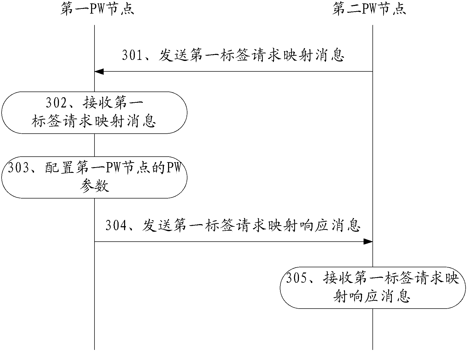
[0112] Based on the method for configuring pseudowire PW parameters provided by the above-mentioned embodiments, when the first PW node learns the first PW parameters of the second PW node, both the first PW node and the second PW node can first initiate a request, that is, to The peer sends a label request mapping message. As long as the interfaces of the first PW node and the second PW node are connected, both the first PW node and the second PW node can initiate a request at the first time.
[0113] In the following embodiments of the present invention, the method is specifically described by using an interactive process in which the first PW node learns the first PW parameters of the second PW node in various situations.
[0114] Specific as image 3 As shown, in the scenario where the second PW node configures the PW parameters of the first PW node, after the first PW node accesses the network, the second PW node actively negotiates the PW parameters with the first PW no...
Embodiment 3
[0138] Based on the method for configuring pseudowire PW parameters provided in the foregoing embodiments, this embodiment of the present invention provides a first PW node that implements the method for configuring pseudowire PW parameters described above. Specifically, as Figure 7 As shown, the first PW node includes: a receiving unit 71 , a processing unit 72 and a sending unit 73 .
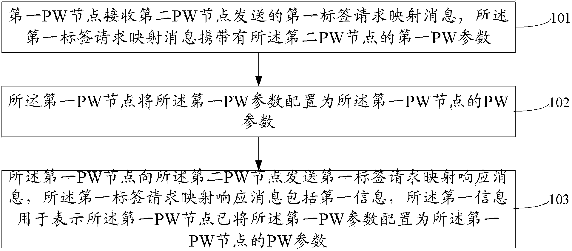
[0139] The receiving unit 71 is configured to receive a first label request mapping message sent by a second PW node, where the first label request mapping message carries a first PW parameter of the second PW node.
[0140] The processing unit 72 is configured to configure the first PW parameter as the PW parameter of the first PW node.
[0141] The sending unit 73 is configured to send a first label request mapping response message to the second PW node, where the first label request mapping response message includes first information, and the first information is used to indicate that the ...
PUM
 Abstract
Description
Claims
Application Information
 - R&D
- Intellectual Property
- Life Sciences
- Materials
- Tech Scout
- Unparalleled Data Quality
- Higher Quality Content
- 60% Fewer Hallucinations
Browse by: Latest US Patents, China's latest patents, Technical Efficacy Thesaurus, Application Domain, Technology Topic, Popular Technical Reports.
© 2025 PatSnap. All rights reserved.Legal|Privacy policy|Modern Slavery Act Transparency Statement|Sitemap|About US| Contact US: help@patsnap.com


