
A Momentum Wheel Based on Ring Motor

A momentum wheel and annular technology, applied in the field of momentum wheel, can solve problems such as large running fluctuation, complex driving circuit, running fluctuation, etc., and achieve the effect of small running fluctuation, strong controllability and simple magnetic circuit.

Active Publication Date: 2017-02-15
XI AN JIAOTONG UNIV
View PDF3 Cites 0 Cited by
  • Summary
  • Abstract
  • Description
  • Claims
  • Application Information

AI Technical Summary

Problems solved by technology

Its disadvantage as a momentum wheel: it is necessary to measure the position of the motor rotor during operation to adjust the input current waveform and phase of the motor, so a complex drive circuit is required; due to the current commutation, the operation fluctuates greatly, especially at low speeds. Not good; the torque during actual operation is not large, so it cannot be applied to situations with high torque requirements
Since this kind of motor also uses a three-phase square wave current, it is also necessary to measure the position of the rotor when the motor is running, which increases the complexity of the motor control circuit; at the same time, there is also the problem of operational fluctuations

Method used


Image

  • A Momentum Wheel Based on Ring Motor
  • A Momentum Wheel Based on Ring Motor
  • A Momentum Wheel Based on Ring Motor

Examples


Embodiment Construction

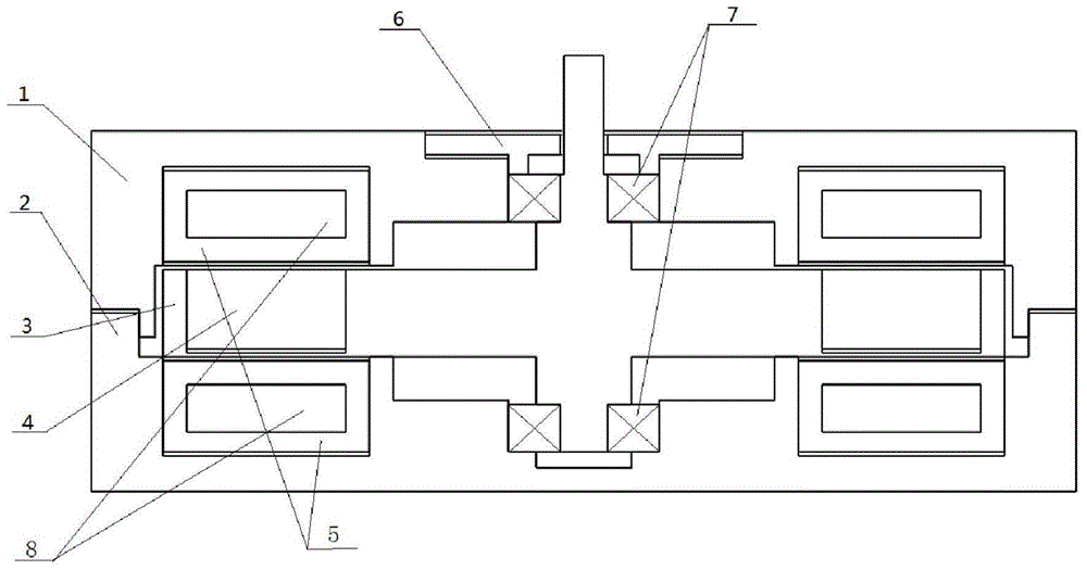
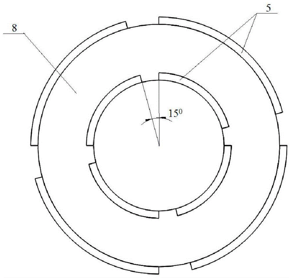
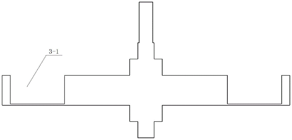
[0021] Combine below figure 1 , figure 2 , image 3 The present invention is further described in detail with specific examples.

[0022] Such as figure 1 , figure 2 and image 3 As shown, a momentum wheel based on a ring motor in the present invention includes a housing base 2, a housing upper cover 1 fixed on the housing base 2, a cavity is formed between the housing upper cover 1 and the housing base 2, and a cavity is arranged in the cavity A permanent magnet tray 3, the periphery of the permanent magnet tray 3 is an annular groove 3-1, and an integral permanent magnet 4 is placed in the annular groove 3-1, and its magnetization direction is axial, that is, the upper magnetic pole is N Pole or S pole, the following magnetic pole is S pole or N pole, the permanent magnet 4 and the permanent magnet tray 3 are the rotor part of the motor, between the upper and lower parts of the permanent magnet 4, the upper cover 1 of the housing and the base 2 of the housing The sta...


PUM


Abstract

A momentum wheel based on a ring motor, comprising a housing base, a housing upper cover fixed thereon, a cavity is formed between the housing upper cover and the housing base, a permanent magnet tray is arranged in the cavity, and an annular groove is formed around the permanent magnet tray. An integral permanent magnet is placed in the annular groove, and its magnetization direction is axial. In the upper and lower cavities of the permanent magnet, an iron core pressed by a silicon steel sheet and a winding coil wound on it are arranged. The middle of the permanent magnet tray The upper and lower parts of the part are respectively connected with the rotating parts of the upper and lower rotating shafts, and the top of the middle part protrudes from the upper cover of the housing for the measurement of the speed and torque; during the operation of the momentum wheel of the present invention, the input is a single-phase DC voltage , the current in the coil is relatively stable, and the operation fluctuation is small; since the momentum wheel uses a whole piece of permanent magnet as the rotor, and the permanent magnet is made of strong magnetic NdFeB material, the electromagnetic field strength of the part where the coil is located is relatively high, and the momentum wheel is relatively stable. High torque can still be provided at low current.

Description

technical field [0001] The invention relates to the technical field of momentum wheels, in particular to a momentum wheel based on a ring motor. Background technique [0002] The existing momentum wheels mainly use brushless DC motors as the power source. The working principle of these DC motors is: the stator is a coil wound iron core, the coil is wound in a three-phase manner, and the three-phase DC power is fed into the power supply. The DC waveform is a square wave, three-phase The phase difference between them is 120 degrees. When working, a current is applied to generate a rotating magnetic field between the coil and the air gap of the permanent magnet of the rotor to drive the permanent magnet to rotate. Its disadvantage as a momentum wheel: it is necessary to measure the position of the motor rotor during operation to adjust the input current waveform and phase of the motor, so a complex drive circuit is required; due to the current commutation, the operation fluctu...

Claims


Application Information

Patent Timeline
Patent Type & Authority Patents(China)
IPC IPC(8): H02K1/22H02K1/12
Inventor 孙剑郭彦昊
Owner XI AN JIAOTONG UNIV
Learn More