
An autonomous power system architecture and its operation control method

A power system and operation control technology, applied to electrical components, circuit devices, AC network circuits, etc., to achieve reliable operation, ensure safety, and improve stability and reliability

Active Publication Date: 2017-07-14
STATE GRID CORP OF CHINA +3
View PDF3 Cites 0 Cited by
  • Summary
  • Abstract
  • Description
  • Claims
  • Application Information

AI Technical Summary

Problems solved by technology

However, these concepts and methods cannot deal with the future high complexity and uncertainty grid

Method used


Image

  • An autonomous power system architecture and its operation control method
  • An autonomous power system architecture and its operation control method
  • An autonomous power system architecture and its operation control method

Examples


Embodiment Construction

[0056] The specific implementation manners of the present invention will be further described in detail below in conjunction with the accompanying drawings.

[0057] The invention is based on the autonomous unit and adopts the target guidance technology to realize the real-time dynamic allocation of the top-level target of the power system, the intelligent selection of the sub-target of the autonomous unit, the coordination and autonomous operation of the autonomous unit, and then realize the autonomous operation control of the entire power system. The specific description is as follows:

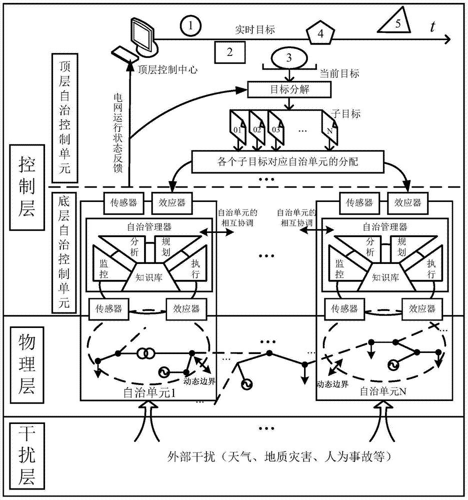
[0058] Such as figure 1 As shown, it is a schematic diagram of the operation control architecture of the autonomous power system designed in the present invention. It mainly includes three parts, autonomous power system control layer, physical layer and external interference layer. Among them, the autonomous power system control layer includes a top-level autonomous control unit and a bott...


PUM


Abstract

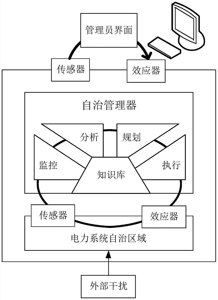
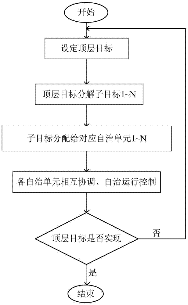
The invention relates to an autonomous electrical power system framework and an operation control method thereof. The autonomous electrical power system framework comprises a control layer, a physical layer and an interfering layer, wherein the physical layer is a practical autonomous electrical power system, and the interfering layer is an interference factor outside a practical autonomous electrical power system. The operation control method includes that an autonomous electrical power system top layer control center sets a top layer target; a target distributing unit resolves the top layer target according to a target instruction and power grid real-time monitoring information; the target distributing unit distributes a sub-target to a corresponding autonomous unit; a base-layer autonomous unit determines and executes an autonomous unit control target, an optimal autonomous area, an autonomous unit coordination scheme and an autonomous operation scheme according to the sub-target; real-time operation states of the autonomous electrical power system are fed back, according to self-requirements, the autonomous unit autonomously achieves self-configuration, self-optimization, self-protection and self-recovery of the autonomous area, and the autonomous unit and the top layer control center check whether the target is achieved.

Description

technical field [0001] The invention belongs to the operation control technology of smart grid, and specifically relates to an autonomous power system architecture and an operation control method thereof. Background technique [0002] In order to cope with energy depletion, a huge renewable energy network and a controllable unit system will be built in the future power system to achieve low-carbon and efficient operation of the system. A large number of renewable power generation units, energy storage units, mobile charging and discharging devices, and power electronic devices will become the main features of the future power system. This advanced future grid configuration will also make its operation control more uncertain and complex. The uncertainty in the system mainly comes from the two-way interaction of the load side, the access of electric vehicles and microgrids, etc., and the complexity mainly comes from the large number of interactive behaviors in the power system...

Claims


Application Information

Patent Timeline
Patent Type & Authority Patents(China)
IPC IPC(8): H02J3/00
Inventor 刘广一高波张凯舒彬周彤曲延滨杨占勇范士雄杨洋
Owner STATE GRID CORP OF CHINA
Learn More