
A Compensation Method for Mems Gyro Drift Error Based on Mems Coupling

A technology of gyro drift and compensation method, which is applied in the field of inertial navigation, can solve the problems of large drift error, low precision of MEMS gyro, and low accuracy of attitude calculation, and achieve remarkable progress, reduce drift error, and improve the effect of attitude calculation accuracy

Active Publication Date: 2016-10-05
HUBEI SANJIANG AEROSPACE HONGFENG CONTROL
View PDF4 Cites 0 Cited by
  • Summary
  • Abstract
  • Description
  • Claims
  • Application Information

AI Technical Summary

Problems solved by technology

[0003] Aiming at the defects of the prior art, the purpose of the present invention is to provide a method for compensating the MEMS gyro drift error based on the coupling of the meter, aiming at solving the problem that the accuracy of the attitude calculation is relatively low due to the low precision of the MEMS gyro and the large drift error in the prior art. low technical issues

Method used


Image

  • A Compensation Method for Mems Gyro Drift Error Based on Mems Coupling
  • A Compensation Method for Mems Gyro Drift Error Based on Mems Coupling
  • A Compensation Method for Mems Gyro Drift Error Based on Mems Coupling

Examples


Embodiment Construction

[0027] In order to make the object, technical solution and advantages of the present invention clearer, the present invention will be further described in detail below in conjunction with the accompanying drawings and embodiments. It should be understood that the specific embodiments described here are only used to explain the present invention, not to limit the present invention.

[0028] The MEMS gyro drift error compensation method based on the meter coupling provided by the present invention solves the problem that the accuracy of the attitude calculation is low due to the low precision of the MEMS gyro and the large drift error, and cannot satisfy engineering applications.

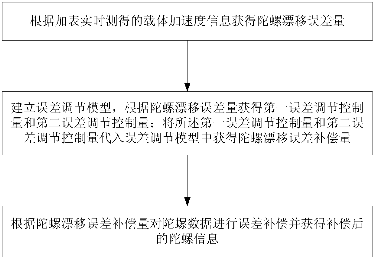
[0029] Such as figure 1 As shown, the compensation method for the MEMS gyro drift error based on the meter coupling provided by the embodiment of the present invention includes the following steps:

[0030] Step 1: Calculate the gyro drift error amount according to the carrier acceleration informatio...


PUM


Abstract

The invention discloses a compensation method for MEMS (Micro-electromechanical Systems) gyroscopic drifting errors based on accelerometer coupling. The compensation method comprises the following steps: (1) a gyroscopic drifting error amount delta omega (t) is obtained according to carrier accelerated speed information which is measured in real time according to an accelerometer; (2) an error adjusting model omega C (t)=delta omega P+delta omega I is established; a first error adjusting control amount delta omega P and a second error adjusting control amount delta omega I are obtained according to formulas delta omega P=KP*delta omega (t) and delta omega I =delta omega I+KI*dt*delta omega (t), and the gyroscopic drifting error amount delta omega (t); the first error adjusting control amount delta omega P and the second error adjusting control amount delta omega I are substituted into the error adjusting model to obtain a gyroscopic drifting error compensation amount omega C (t); (3) error compensation is carried out on gyroscopic data according to the gyroscopic drifting error compensation amount to obtain compensated gyroscopic information. According to the compensation method disclosed by the invention, the problems that the posture resolving precision is low and engineering applications cannot be met caused by low gyroscopic precision of MEMS and large accumulated drifting errors are solved; the MEMS gyroscopic drifting can be inhibited and the posture resolving precision is improved; the compensation method has high engineering application values and promotional values.

Description

technical field [0001] The invention belongs to the technical field of inertial navigation, and more specifically relates to a method for compensating MEMS gyro drift errors based on meter-added coupling. Background technique [0002] In the inertial navigation system, the information processing of gyroscope and accelerometer (plus meter) is directly related to the calculation accuracy of the carrier attitude, and the attitude is an important parameter reflecting the movement of the carrier. Tracking, motion trajectories, performance analysis, etc. have an important impact. Usually the attitude solution is to calculate the carrier attitude matrix in real time according to the data of the gyroscope and the speed and position information of the carrier, so as to realize the real-time follow-up of the navigation coordinate system to the geographic coordinate system and the solution of the carrier attitude. However, due to the limited accuracy of gyroscopes and accelerometers, ...

Claims


Application Information

Patent Timeline
Patent Type & Authority Patents(China)
IPC IPC(8): G01C25/00
CPCG01C25/005
Inventor 焦守江翁海诠陈薇王勇刚潘静李永江
Owner HUBEI SANJIANG AEROSPACE HONGFENG CONTROL
Learn More