Dry-laying type floor heating structure and laying method thereof

A laying method and dry laying technology are applied to the dry laying floor heating structure and its laying field, which can solve the problems of troublesome maintenance, high cost and slow heating, and achieve the effects of uniform and rapid heating, low use cost and standardized laying.

Inactive Publication Date: 2014-10-29
HANGZHOU SHENGPIN HEATING & COOLING EQUIP
View PDF2 Cites 2 Cited by
  • Summary
  • Abstract
  • Description
  • Claims
  • Application Information

AI Technical Summary

Problems solved by technology

[0002] With the continuous advancement of science and technology, people's living standards continue to improve, and the quality of life is also improving day by day. Various household heating devices such as air conditioners and floor heating are becoming more and more popular. Air conditioners will absorb a lot of water in the room, often causing dry mouth and other body water shortages, and more serious cases of "air conditioning disease". Therefore, household floor heating devices are more and more popular among families with economic conditions. However, due to its own structure, the existing floor heating device will occupy a certain room height, and it cannot be laid with pure solid wood floor. In addition, because it is difficult to standardize the laying, the heating is slow and random, and it is difficult to carry out systematically and rationally. control, resulting in high cost and troublesome maintenance

Method used


Image

  • Dry-laying type floor heating structure and laying method thereof
  • Dry-laying type floor heating structure and laying method thereof

Examples


Embodiment Construction

[0021] The present invention will be described in further detail below in conjunction with the accompanying drawings, but it is not intended to limit the protection scope of the present invention.

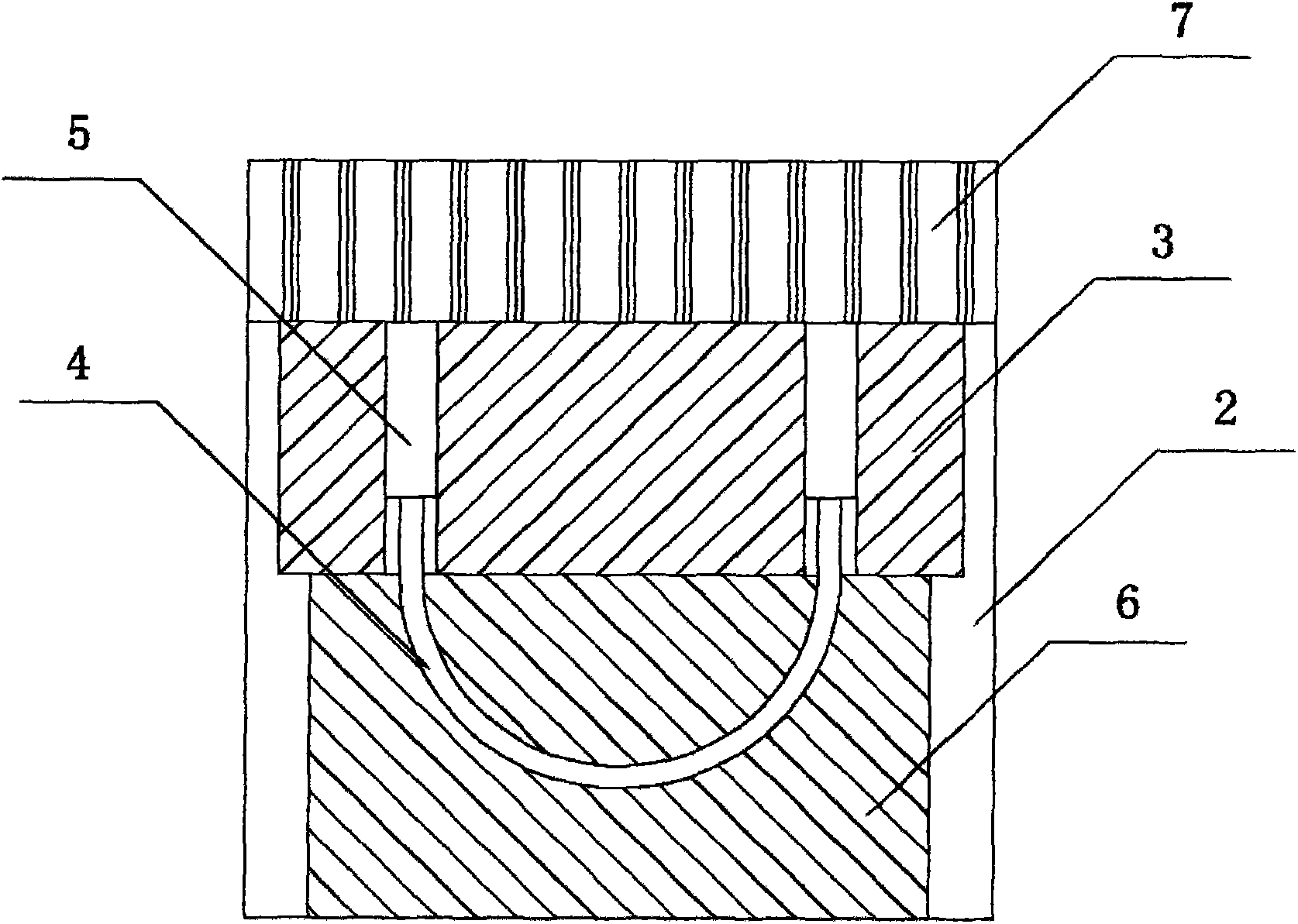
[0022] Such as figure 1 with 2 As shown, a dry floor heating structure includes a number of keels 2 laid in parallel on the ground 1, and a heat conducting plate 3 is laid between every two keels 2. The heat conducting plate 3 is a far-infrared carbon crystal plate, and the heat conducting plates 3 are two The end is lapped on the keel 2, and the middle part of the heat conduction plate 3 is fixedly laid with a water pipe 4. The water pipe 4 and the heat conduction plate 3 are fixed by a fixing belt 5. The water pipe 4 is a special PEX pipe for floor heating, and the fixing belt 5 is a far-infrared aluminum belt. Floor 7 is laid on keel 2 . A heat insulating layer 6 is laid between the heat conducting plate 3 and the ground 1 .

[0023] Laying method of the present invention, it...


PUM


Abstract

The invention belongs to the field of building heating, and particularly relates to a dry-laying type floor heating structure. The dry-laying type floor heating structure comprises a plurality of keels arranged on the ground in parallel, a thermal conductive plate is arranged between every two keels, the two ends of the thermal conductive plates are in lap joint with the keels, water pipes are fixedly laid in the middles of the thermal conductive plates, and the floor is laid on the keels. According to a laying method of the dry-laying type floor heating structure, a plurality of mutually parallel keels are laid on an original floor; an integrated heat insulation carbon crystal plate is laid between every two keels; hot water pipes are laid on the integrated heat insulation carbon crystal plates and are wrapped with far infrared aluminum tape; finally the floor is laid on the keels. According to the dry-laying type floor heating structure, the far infrared carbon crystal plates are laid between every two keels, the occupied space of a room in height is saved, meanwhile heating is even and fast, standard laying can be conducted, control is convenient, and using cost is low; underground jointless special PEX pipes for floor heating are adopted, and the types of floors which can be laid are complete.

Description

technical field [0001] The invention belongs to the field of building heating, and in particular relates to a dry-paved floor heating structure and a laying method thereof. Background technique [0002] With the continuous advancement of science and technology, people's living standards continue to improve, and the quality of life is also improving day by day. Various household heating devices such as air conditioners and floor heating are becoming more and more popular. Air conditioners will absorb a lot of water in the room, often causing dry mouth and other body water shortages, and more serious cases of "air conditioning disease". Therefore, household floor heating devices are more and more popular among families with economic conditions. However, due to its own structure, the existing floor heating device will occupy a certain room height, and it cannot be laid with pure solid wood floor. In addition, because it is difficult to standardize the laying, the heating is slo...

Claims


Application Information

Patent Timeline
Patent Type & Authority Applications(China)
IPC IPC(8): F24D3/14
Inventor 李文同
Owner HANGZHOU SHENGPIN HEATING & COOLING EQUIP
Why Eureka
Try Eureka