Pressure head device of sand jetting mechanism of upper pressing type core making machine

A core making machine and indenter technology, applied in molding machines, manufacturing tools, casting and molding equipment, etc., can solve the problems of loosening and falling off at the fixed part of the hose, large thermal energy loss of catalytic gas, and sand shooting energy loss, etc., to reduce thermal energy. The effect of reducing the loss of sand shot energy and saving the cost of spare parts

Active Publication Date: 2014-10-29
SUZHOU MINGZHI TECH
View PDF5 Cites 9 Cited by
  • Summary
  • Abstract
  • Description
  • Claims
  • Application Information

AI Technical Summary

Problems solved by technology

[0006] 1. The air intake of sand shooting uses a hose to the inside of the pressure head. The hose is exposed and moves with the movement of the pressure head. In actual use, it is easy to cause loosening of the fixed part of the hose, resulting in abnormal equipment
In addition, if the hose interferes with other parts of the equipment, the hose is easy to wear and needs to be replaced and maintained;
[0007] 2. The sand shooting hose moves with the pressure head, and the length needs to reserve a certain amount of movement margin. The pipeline is long, and the sand shooting energy is lost, which reduces the sand shooting effect;
[0008] 3. The cold core blowing uses a hose to the blowing hood or blowing plate. The hose is exposed and the blowing hood or blowing plate moves. During actual use, it is easy to loosen the fixed part of the hose and cause the equipment to be abnormal.
In particular, the hose moves in and out with the blowing hood or blowing plate, which takes up a lot of space and is easy to interfere with other parts of the equipment. The hose is easy to wear and needs to be replaced and maintained;
[0009] 4. The blowing hose moves with the blowing hood of the pressure head, and the length needs to reserve a certain amount of movement margin. The pipeline is long, and the heat loss in the process of catalytic gas transportation is large, which reduces the curing effect.
At the same time, during the use of the hose, it is easy to harden due to the action of the heated catalytic gas and needs to be replaced regularly

Method used


Image

  • Pressure head device of sand jetting mechanism of upper pressing type core making machine
  • Pressure head device of sand jetting mechanism of upper pressing type core making machine
  • Pressure head device of sand jetting mechanism of upper pressing type core making machine

Examples


Embodiment 1

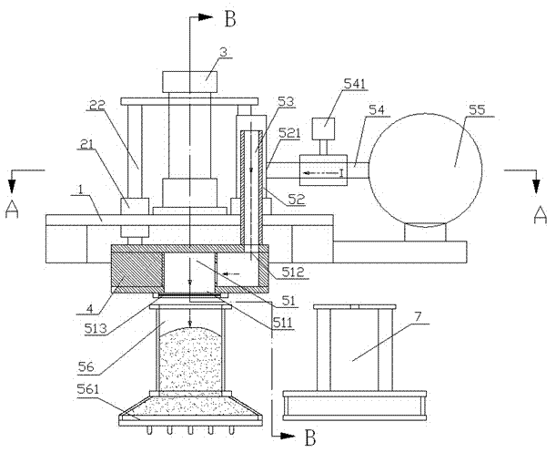
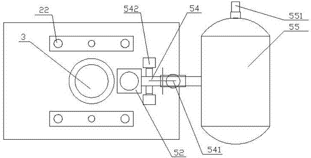
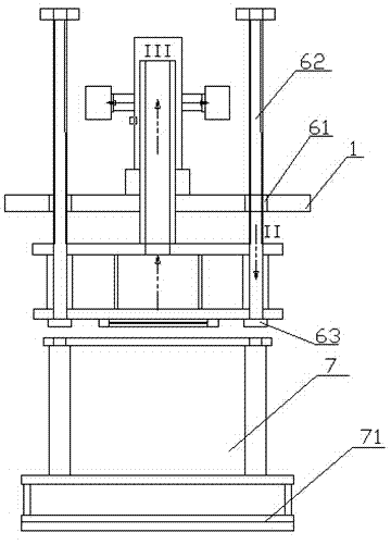
[0041] see Figure 1-Figure 3 , as shown in the legend, a pressure head device of the sand shooting mechanism of the upper pressure core making machine, including:

[0042] A frame is provided with a support plate 11 installed horizontally;

[0043] A lifting guide mechanism, including a guide sleeve 21 assembled on the support plate 11 with the axis perpendicular to the support plate 11, and a guide rod 22 slidingly penetrated in the guide sleeve 21;

[0044] A hydraulic cylinder 3 is installed on the upper side of the support plate 11 and its drive is connected to the upper end of the guide rod 22;

[0045] A pressure head 4 is arranged below the support plate 11 and driven to connect to the lower end of the guide rod 22. The pressure head 4 is also provided with a ventilation flow channel 51, and the ventilation flow channel 51 has a first flow channel port 511 and a second flow channel port. 512, the first flow channel port 511 is located on the pressing surface of the p...

Embodiment 2

[0067] The rest is the same as the first embodiment, except that the upper port of the first ventilation guide sleeve is set as the above-mentioned first ventilation port.

Embodiment 3

[0069] The rest is the same as the first or second embodiment, except that the above-mentioned sand shooting air bag is set on an independent air bag support.


PUM


Abstract

The invention discloses a sand jetting ventilation mechanism of an upper pressing type core making machine. The sand jetting ventilation mechanism of the upper pressing type core making machine comprises a first ventilation guide sleeve and a first ventilation guide pipe, wherein the first ventilation guide sleeve is fixedly mounted on a bracket plate; the axis of the ventilation guide sleeve is perpendicular to the bracket plate; an upper end opening of the first ventilation guide sleeve is sealed; a first ventilation end opening is formed in the side wall of the first ventilation guide sleeve or the upper end opening of the first ventilation guide sleeve serves as the first ventilation end opening; an upper end opening of the first ventilation guide pipe is communicated with the first ventilation guide sleeve; the outer wall of the upper end opening of the first ventilation guide pipe is connected with the inner wall of a lower end opening of the first ventilation guide sleeve in a sealing and guiding manner; the lower end opening of the first ventilation guide pipe is fixedly communicated with a second runner end opening. By virtue of the sand jetting ventilation mechanism of the upper pressing type core making machine, the reliability of the sand jetting ventilation mechanism and a curing ventilation mechanism is improved, the costs of spare parts are reduced, the length of a sand jetting and curing pipeline is reduced, the sand jetting and curing energy loss is reduced, the sand jetting and curing effect is improved, the gas heat energy loss is reduced, the consumption of catalyst and air is reduced, and the overall reliability of the core making machine is improved.

Description

technical field [0001] The invention relates to a pressure head device, in particular to a pressure head device of a sand-shooting mechanism of an upper-press type core making machine. Background technique [0002] The main core-making process of the upper-pressure core-making machine is generally divided into the sand-shooting process and the curing process. [0003] In the sand shooting process, the upper head device is used to press the lower shot head, and then the molding sand is filled into the core box from the shot head through the mold shooting plate by compressed air. At present, the general core making machine connects the air bag and the inside of the head through a hose. The compressed air in the air bag enters the inside of the pressure head to form a sand injection inlet channel. [0004] The curing process can be divided into hot core and cold core. The cold core uses the upper pressure head device to press the lower blowing cover or blowing plate, and then ...

Claims


Application Information

Patent Timeline
Patent Type & Authority Applications(China)
IPC IPC(8): B22C15/23
Inventor 王鼎铭顾海兵徐磊磊王直良
Owner SUZHOU MINGZHI TECH
Why Eureka
Try Eureka