A special riveting joint for blind rivet nuts

A technology of riveting nuts and riveting joints, which is applied in the field of riveting devices and can solve problems such as inability to pull riveting rivets

Active Publication Date: 2016-06-08
苏州富士特金属薄板制品有限公司
View PDF6 Cites 1 Cited by
  • Summary
  • Abstract
  • Description
  • Claims
  • Application Information

AI Technical Summary

Problems solved by technology

[0007] The purpose of the present invention is to provide a special riveting joint for rivet nuts, to solve the problem that existing rivet guns or riveting joints cannot rivet rivets with larger nominal diameters

Method used


Image

  • A special riveting joint for blind rivet nuts
  • A special riveting joint for blind rivet nuts
  • A special riveting joint for blind rivet nuts

Examples


Embodiment approach

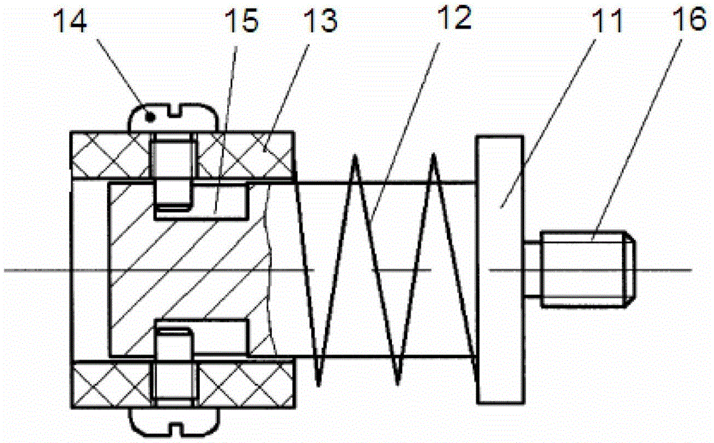
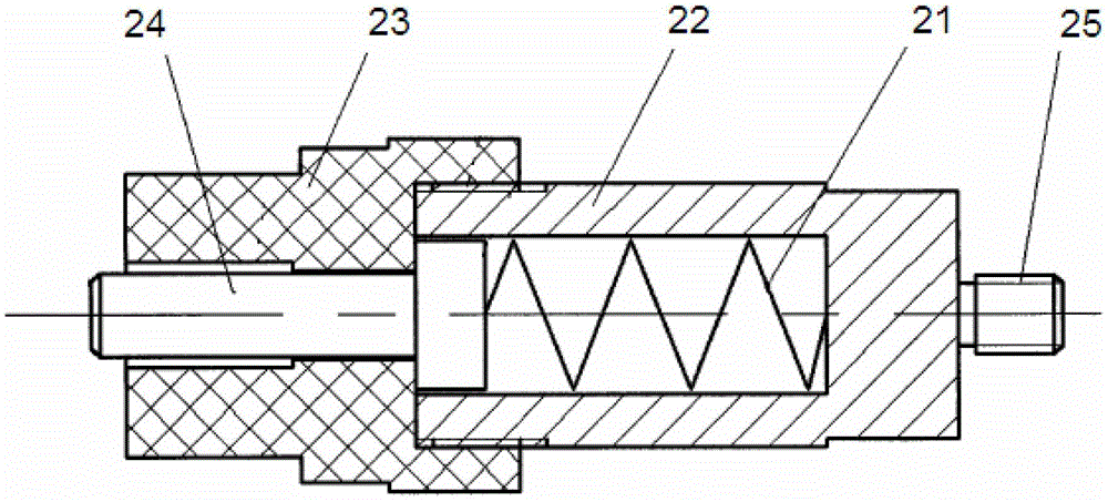
[0034] In further embodiments of the present invention, please continue to refer to Figure 4 to Figure 6 shown. There is also a bearing guide 71 closely attached to the two ends of the plane bearing 7, and the two bearing guides 71 are sleeved on the screw rod 4 together with the plane bearing 7, and the two bearing guides 71 and the plane bearing 7 are located between the nut lock sleeve 6 and the plane bearing 7. Between the positioning sleeves 5.

[0035] In a further embodiment of the present invention, there is also a spacer 8 between the plane bearing 7 and the locking nut sleeve 6, and the spacer 8 is sleeved on the screw rod 4, so that the plane bearing 7 can be protected when the locking nut sleeve 6 rotates. , and easy to replace.

[0036] In a further embodiment of the present invention, a screw 9 is provided on an end surface of the locking nut sleeve 6 facing away from the spacer 8 . After the screw rod 4 is connected with the nut locking sleeve 6, the screw 9...


PUM


Abstract

The invention discloses a special rivet joint for blind rivet nuts, which includes: a screw rod, one end of which is used to connect with an external rivet to pull the external rivet; a positioning sleeve, the positioning sleeve is fixedly sleeved In the middle of the screw rod; a nut lock sleeve, the nut lock sleeve is threaded with the other end of the screw rod opposite to the external rivet to control the forward or reverse rotation of the screw rod, and the nut is locked The sleeve is close to the positioning sleeve; it also includes: a plane bearing, the plane bearing is sleeved on the screw rod, and the plane bearing is located between the positioning sleeve and the nut locking sleeve, reducing the nut The friction force generated when the locking sleeve turns. Using the special riveting head for blind rivet nuts of the present invention, after matching the riveting head with an external riveting gun, the rivet with a larger nominal diameter can be effectively riveted through the screw rod.

Description

technical field [0001] The invention relates to a riveting device, in particular to a special riveting head for blind rivet nuts. Background technique [0002] Riveting is a very widely used connection method today, especially in the field of aerospace, where a large number of riveting processes are required in the assembly process of products. Due to the narrow internal space of the actual product, the openness of the structure of many parts is poor, and the indenter of the riveting machine cannot be entered for riveting. These parts often need to use the riveting process. [0003] figure 1 It is a schematic diagram of the riveting head of the patent number 201120366468.4, figure 2 It is a schematic diagram of the auxiliary riveting joint of the patent number 201120366468.4. See figure 1 As shown, the riveting head includes a mandrel 11 , a spring 12 , a limiting cylinder 13 and a screw 14 . One end of the mandrel 11 is close to the radial position of the head, and tw...

Claims


Application Information

Patent Timeline
Patent Type & Authority Patents(China)
IPC IPC(8): B21J15/38
Inventor 刘安荣
Owner 苏州富士特金属薄板制品有限公司
Why Eureka
Try Eureka