Eureka AIR delivers breakthrough ideas for toughest innovation challenges, trusted by R&D personnel around the world.

Yarn draw-off unit of a rotor spinning machine and method for producing a yarn with the aid of a rotor spinning machine

A technology of rotor spinning machine and yarn, which is applied in the direction of spinning machine, open-end spinning machine, continuous winding spinning machine, etc., and can solve the problems of false twist strength limit and so on

Inactive Publication Date: 2014-10-22
MASCHINENFABRIK RIETER AG
View PDF10 Cites 4 Cited by
  • Summary
  • Abstract
  • Description
  • Claims
  • Application Information

AI Technical Summary

Problems solved by technology

[0004] Even if the protruding structures are fully capable of positively influencing the fiber bonding process, fundamentally the strength of the false twist is limited

Method used


Image

  • Yarn draw-off unit of a rotor spinning machine and method for producing a yarn with the aid of a rotor spinning machine
  • Yarn draw-off unit of a rotor spinning machine and method for producing a yarn with the aid of a rotor spinning machine
  • Yarn draw-off unit of a rotor spinning machine and method for producing a yarn with the aid of a rotor spinning machine

Examples


Embodiment Construction

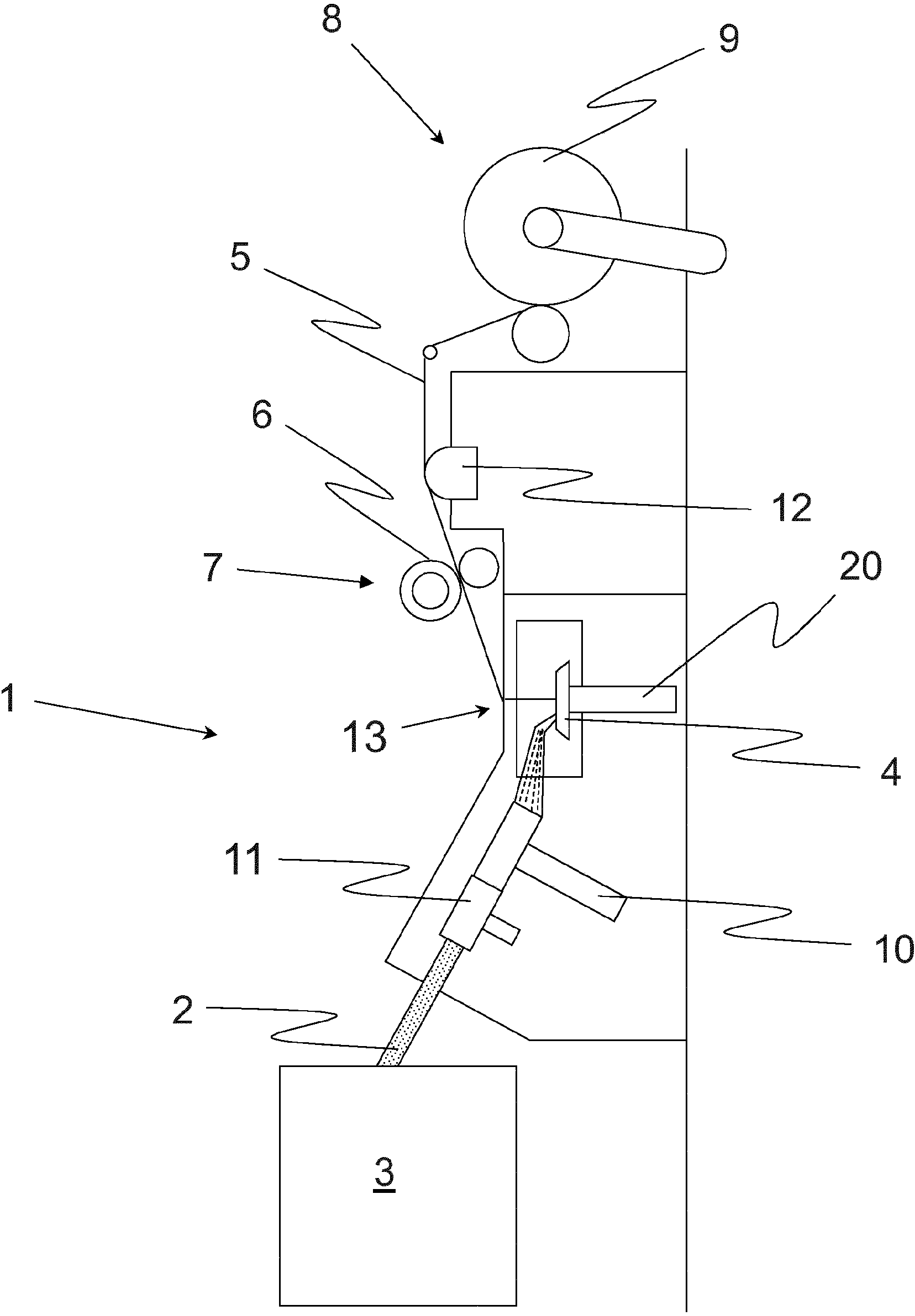
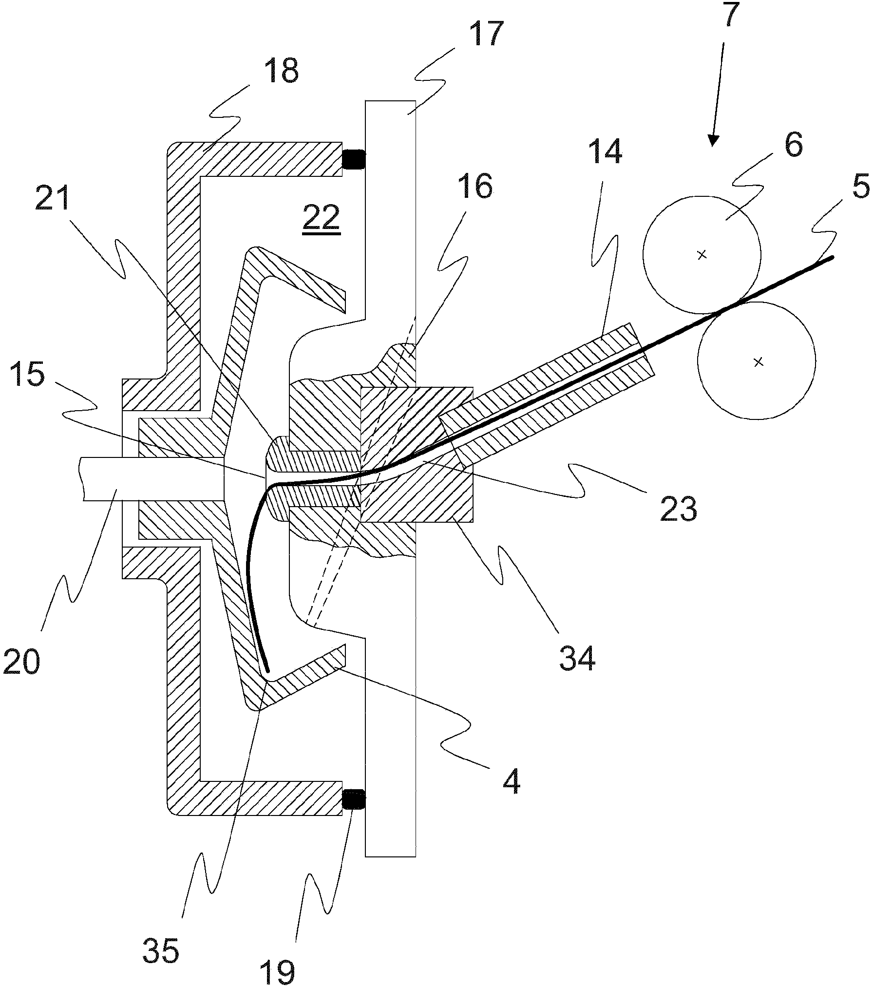
[0035] figure 1 Shown is a partial sectional side view of a known rotor spinning machine, which typically comprises a plurality of spinning positions 1 mounted side by side in the longitudinal direction of the machine, ie in the vertical aspect of the plane. In a known manner, the fiber material 2 coming out of the spinning drum 3 will be conveyed to the individual spinning positions 1 by means of a supply device 11, and by means of an opening roller 10, said fiber material 2 will be carded into individual strands. fiber, then, through figure 2 The fiber supply duct 16 (appearing behind the plane of the paper) marked with dashed lines, the fiber material 2 is to be fed to the spinning rotor 4 . The yarn 5 produced on said spinning rotor 4 is drawn from the spinning position 1 via the outlet 13 by the yarn delivery device 7 contained in the yarn delivery roller pair 6 and checked, if possible, with a yarn monitoring unit 12 The yarn defect is then wound up by the take-up dev...


PUM


Abstract

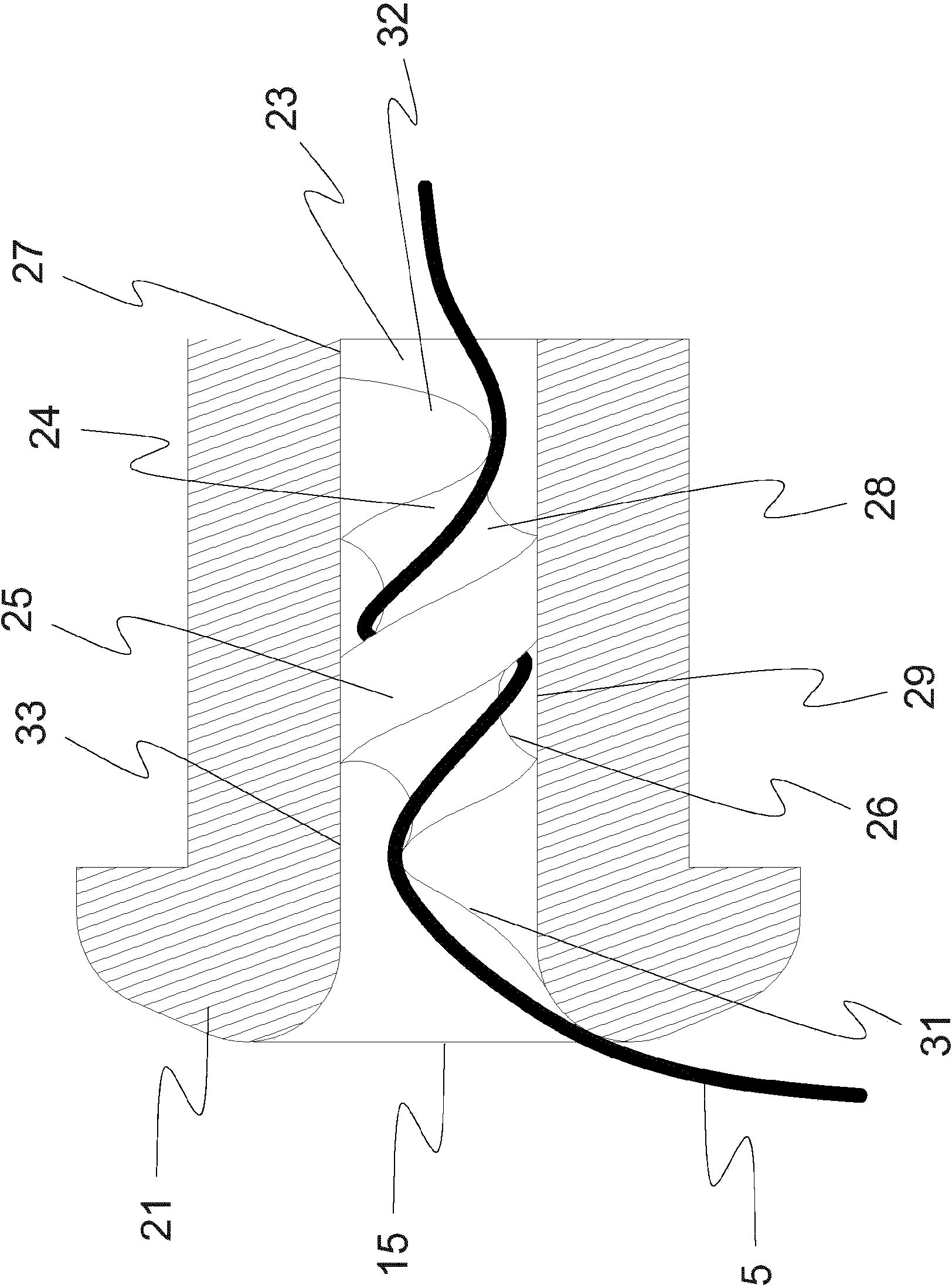
The invention relates to a yarn draw-off unit of a rotor spinning machine, having a draw-off nozzle (21) which projects into a spinning chamber (22) of the rotor spinning machine, and a draw-off conduit (23) for a yarn (5) produced within the spinning chamber (22), the draw-off conduit (23) being arranged downstream of the draw-off nozzle (21) in the draw-off direction of the yarn (5) that is drawn off from the spinning chamber (22). The draw-off conduit (23) comprises a helical section (24), with the aid of which a false twist can be imparted to the yarn (5) within the draw-off conduit (23). Furthermore, a draw-off nozzle for a rotor spinning machine is described, the draw-off conduit (23) of which comprises a helical section (24), with the aid of which a false twist can be imparted to the yarn (5) within the draw-off nozzle (21). Finally, the invention relates to a method for producing a yarn (5) with the aid of a rotor spinning machine. The method is characterised in that the yarn (5) is exposed to torque within a helical section (24) of the draw-off conduit (23), said torque causing the yarn (5) to rotate about its longitudinal axis, the direction of rotation of the rotation corresponding to the direction of rotation that is imparted to the yarn (5) by the spinning rotor (3).

Description

field of invention [0001] The invention relates to a yarn drawing unit of a rotor spinning machine, which includes a yarn drawing nozzle extending into the spinning chamber of the rotor spinning machine, and a drawing nozzle for drawing out the yarn generated in the spinning chamber. A yarn bobbin, wherein, in the yarn-drawing direction of the yarn drawn out from the spinning chamber, the yarn-drawing bobbin is installed at a position downstream of the yarn-drawing nozzle. Furthermore, the invention provides a method for producing said yarn by means of a rotor spinning machine, in which, in the spinning chamber of the spinning position, the fiber material consisting of individual fibers is twisted to form a The yarn can then be drawn out of the spinning chamber by means of the yarn delivery nozzle via the yarn delivery tube. Finally, the invention describes a yarn delivery nozzle for use in a rotor spinning machine equipped with a yarn delivery tube structure, via which yarn ...

Claims


Application Information

Patent Timeline
IPC IPC(8): D01H4/40
CPCD01H4/40
Inventor G·斯塔莱克M·巴斯廷
Owner MASCHINENFABRIK RIETER AG
Why Eureka
Eureka Blog
Learn More