A kind of drift tube with support rod and preparation method thereof

A technology for drift tubes and support rods, applied in the field of drift tubes, can solve problems such as difficult processing, achieve the effects of improving surface finish, increasing acceleration gradient, and reducing the maximum surface electric field

Active Publication Date: 2016-09-14
CHINA INSTITUTE OF ATOMIC ENERGY
View PDF7 Cites 0 Cited by
  • Summary
  • Abstract
  • Description
  • Claims
  • Application Information

AI Technical Summary

Problems solved by technology

[0010] In order to solve the existing drift tube and support rod structure and the problems of high processing difficulty and other problems in the preparation process, the present invention provides a drift tube with a support rod and a preparation method thereof

Method used


Image

  • A kind of drift tube with support rod and preparation method thereof
  • A kind of drift tube with support rod and preparation method thereof
  • A kind of drift tube with support rod and preparation method thereof

Examples


Embodiment 1

[0034] A drift tube with a support rod, the processing method of which is as follows:

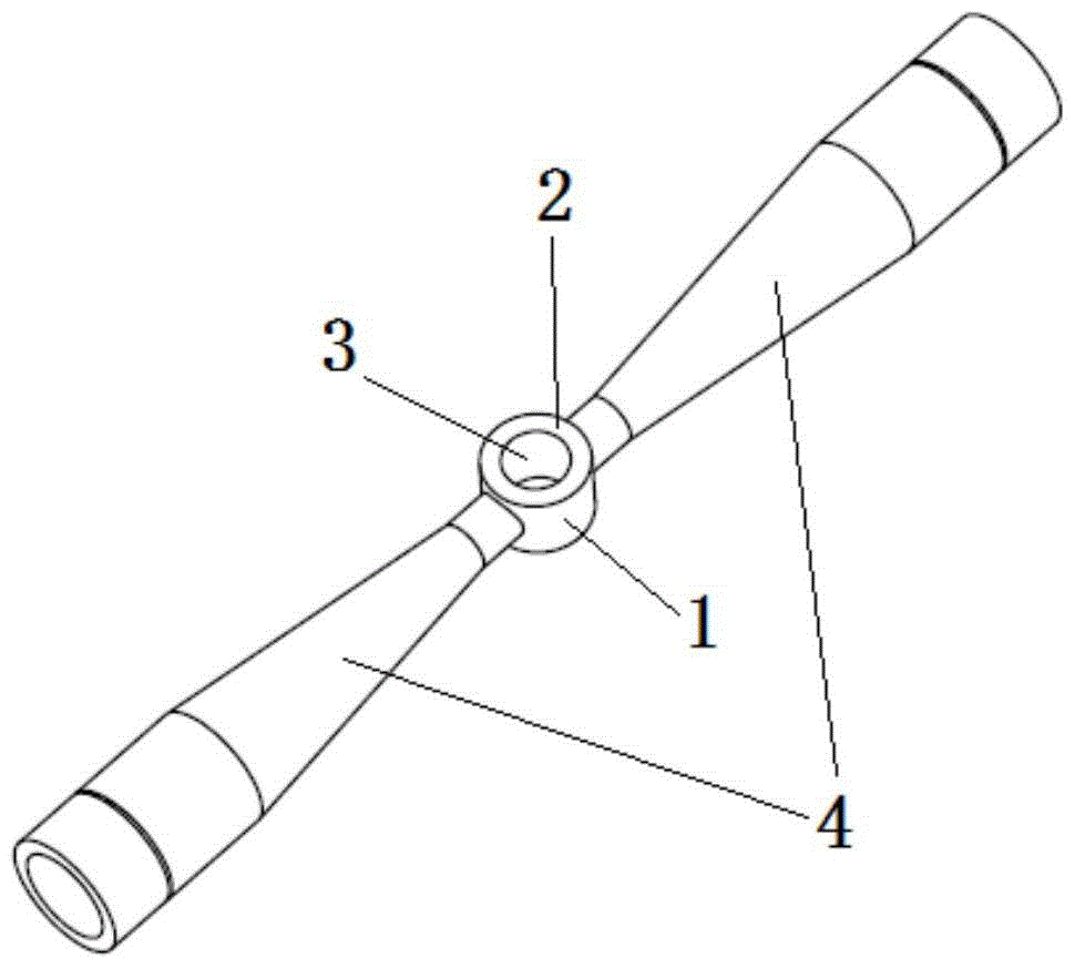
[0035] 1. Use a lathe to turn the blank into a support rod 4 connected with a sphere;

[0036] 2. Process two sections 2 on the sphere;

[0037] 3. Remove a cylinder whose axis is the line connecting the centers of the two cross-sections 2 to form the beam channel 3 and obtain the drift tube 1;

[0038] 4. Process the cooling water flow channel on the drift tube 1, then seal the opening part necessary for processing by welding, and polish the welding part;

[0039] 5. Process the cooling water channel connected to the cooling water channel of the drift tube inside the support rod 4 .

Embodiment 2

[0041] A drift tube with a support rod, the processing method of which is as follows:

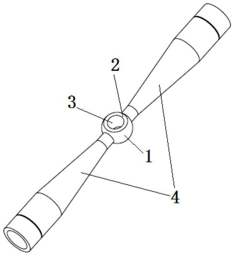
[0042] 1. Use a lathe to turn the blank into a support rod 4 connected with a sphere;

[0043] 2. Process two sections 2 on the spheroid;

[0044] 3. Remove a cylinder whose axis is the line connecting the centers of the two cross-sections 2 to form the beam channel 3 and obtain the drift tube 1;

[0045] 4. Process the cooling water flow channel on the drift tube 1, then seal the opening part necessary for processing by welding, and polish the welding part;

[0046] 5. Process the cooling water flow channel connected with the cooling water flow channel of the drift tube inside the support rod 4 .

[0047] The drift tubes with support rods prepared by the processing methods of Examples 1 and 2 were applied to accelerators. When the accelerator is working, the heat generated by the loss of the radio frequency field on the surface of the drift tube and the support rod is very conveniently ...


PUM


Abstract

The invention relates to a component of a linear accelerator. In order to solve the existing drift tube and support rod structure and the problems of high processing difficulty in the preparation process thereof, the present invention provides a drift tube with a support rod and a preparation method thereof. The three-dimensional structure of the drift tube is as follows: first , on the basis of a sphere or a spheroid, symmetrically cut off two equal-sized parts of the sphere or a spheroid with a pair of parallel planes, then process a beam flow channel, and prepare a cooling water channel on the remaining structure; the support rod There is a cooling water flow channel connected with the cooling water flow channel of the drift tube inside. The drift tube of the present invention adopts a shape based on a sphere or a spheroid, so the integrated processing of the drift tube and the support rod is realized more conveniently. At the same time, the welding operation of the present invention is simple, avoids the difficulties existing in the complicated welding process, improves the surface smoothness of the drift tube, and is beneficial to improving the acceleration gradient of the acceleration chamber.

Description

technical field [0001] The invention relates to a component of a linear accelerator, in particular to a drift tube with a support rod. Background technique [0002] The standing wave resonant cavity linear accelerator is a commonly used classical accelerator, which is divided according to the type of particle acceleration, mainly including electron accelerators, proton accelerators and heavy ion accelerators. There are many types of standing wave acceleration structures, including edge-coupled accelerators, shaft-coupled accelerators, drift tube linear accelerators, quarter-wavelength accelerators, half-wavelength accelerators, radio frequency quadrupole accelerators, and so on. [0003] For quarter-wavelength accelerator (QWR), half-wavelength accelerator (HWR), drift tube linear accelerator (DTL), interdigitated drift tube linear accelerator (IH-DTL), cross rod drift tube linear accelerator (CH-DTL ) and a spoke accelerator (spoke), one of their common points is that ther...

Claims


Application Information

Patent Timeline
Patent Type & Authority Patents(China)
IPC IPC(8): H05H7/22B23K31/02
Inventor 李金海韩广文张立锋曾自强
Owner CHINA INSTITUTE OF ATOMIC ENERGY
Why Eureka
Try Eureka