
Servo-type acceleration sensor

An acceleration sensor, servo-type technology, applied in the direction of measurement of acceleration, speed/acceleration/shock measurement, instruments, etc., can solve the problems of increased assembly man-hours, non-oriented miniaturization, and large current flow

Active Publication Date: 2014-10-22
RION COMPANY
View PDF6 Cites 0 Cited by
  • Summary
  • Abstract
  • Description
  • Claims
  • Application Information

AI Technical Summary

Problems solved by technology

It is difficult to ensure the gap magnetic field (for example, 5000 Gauss) and the number of turns of the coil pattern (for example, 600 turns) in this part structure, and it requires a large amount of current to flow, so it is difficult to put into practical use
[0006] In addition, in the technology described in Patent Document 2, the flexible plate is respectively fixed to the fixed plate and the movable plate by using “U”-shaped clip parts, so the number of parts increases, and the assembly operation is not easy, and it is not oriented to Miniaturization increases assembly man-hours

Method used


Image

  • Servo-type acceleration sensor
  • Servo-type acceleration sensor
  • Servo-type acceleration sensor

Examples


Embodiment Construction

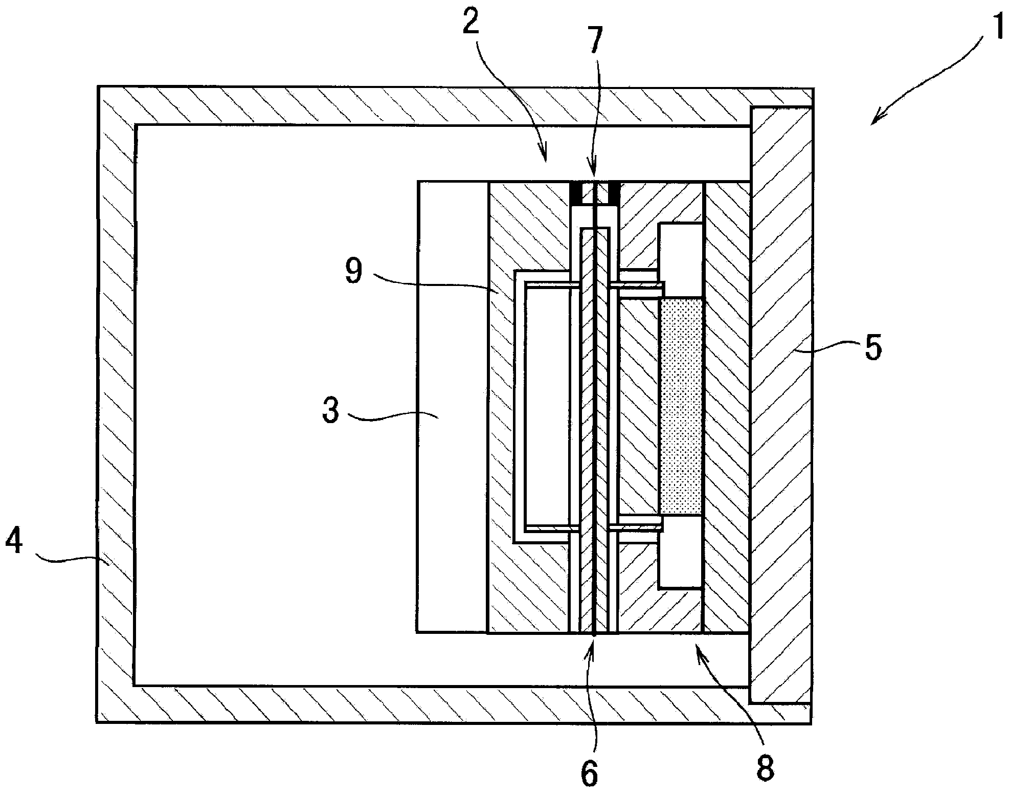
[0039] The implementation of the present invention will be described below with reference to the accompanying drawings. The servo type acceleration sensor 1 of embodiment, as figure 1 As shown, it includes a sensor unit 2 , a servo circuit unit 3 , a housing 4 and a base member 5 . The sensor unit 2 is attached to the base member 5 , and the servo circuit unit 3 is attached to the sensor unit 2 .

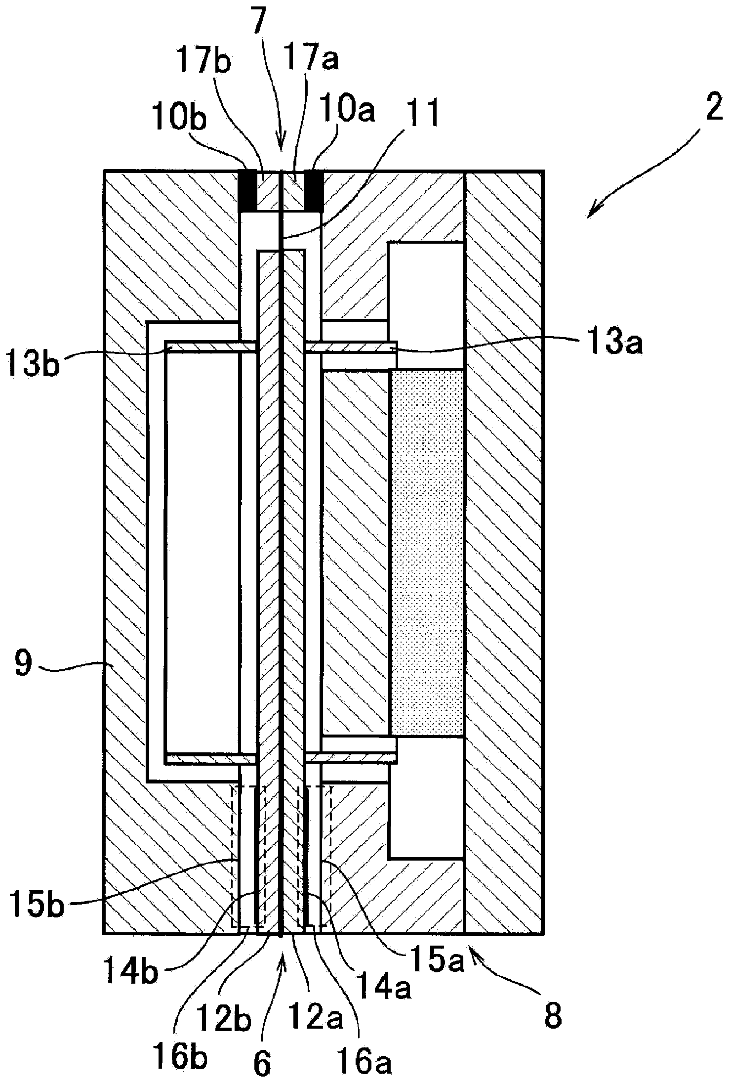
[0040] Such as figure 2 As shown, the sensor part 2 includes a vibrator part 6, a frame part 7, a first housing 8, a second housing 9, two spacers 10a, 10b, and the like. The shape of the sensor unit 2 is substantially cylindrical, with a height of about 15 mm and an outer diameter of about 23 mm.

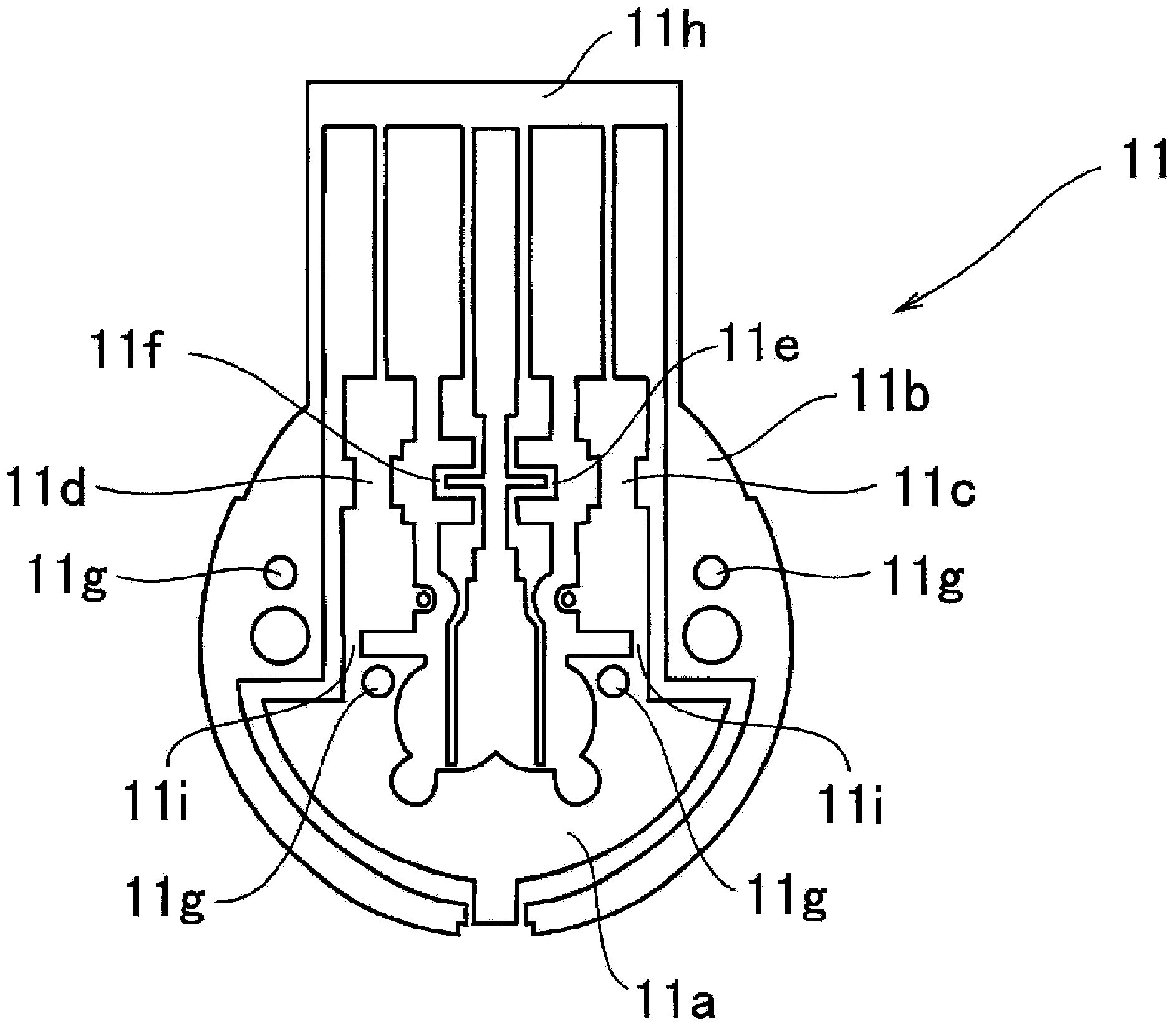
[0041] The vibrator part 6 and the frame part 7 sandwich and bond the thin metal plate member 11 via a pair of vibrator part printed circuit boards 12a, 12b and frame part printed circuit boards 17a, 17b, respectively. Coils 13 a , 13 b are mounted on vibrator portion printed circui...


PUM


Abstract

A servo-type acceleration sensor comprises an oscillator portion (6) moving based on the acceleration, a frame portion (7) supporting the oscillator portion (6), displacement detection portions (16a, 16b) detecting the displacement of the oscillator portion (6) through changes of electrostatic capacitance, and a servo circuit portion that supplies current to a coil (13a) disposed on the oscillator portion (6) on the basis of the changes, detected by the displacement detection portions (16a, 16b), of the electrostatic capacitance, the current being used for controlling displacement of the oscillator portion (6). The current supplied by the servo circuit portion serves as the acceleration and is output. A metal thin sheet part (11) is sandwiched between a pair of printed substrates (12a, 12b) for the oscillator portion so that the oscillator portion (6) is formed, and the metal thin sheet part (11) is also sandwiched between a pair of printed substrates (17a, 17b) for the frame portion so that the frame portion (7) is formed.

Description

technical field [0001] The invention relates to a servo type acceleration sensor used in seismographs and the like. Background technique [0002] In the capacitive servo type acceleration sensor, when acceleration is applied, the vibrator part will be displaced relative to the frame part, but this displacement is detected by the change in electrostatic capacitance, and a current corresponding to the change in electrostatic capacitance flows through the coil equipped in the vibrator part. The electromagnetic force is generated, and the vibrator part appears to be in a static state. Since the current is proportional to the acceleration, the acceleration can be known only by measuring the current. [0003] In Patent Document 1 (Japanese Patent No. 2861694), a servo-type vibration sensor is described in which an oscillator (vibrator part) is constituted by a plurality of substrates on which coil patterns are formed, as a support for the oscillator (vibrator part). body, a flex...

Claims


Application Information

Patent Timeline
Patent Type & Authority Applications(China)
IPC IPC(8): G01P15/125
Inventor 关淳
Owner RION COMPANY
Learn More