Debris flow mechanical parameter monitoring system and debris flow early warning system
A technology of monitoring system and mechanical parameters, applied in disaster monitoring and debris flow prevention and control engineering fields, can solve problems such as not considering the process of coupling to form debris flow, and unable to answer
- Summary
- Abstract
- Description
- Claims
- Application Information
AI Technical Summary
Problems solved by technology
Method used
Image
Examples
Embodiment 1
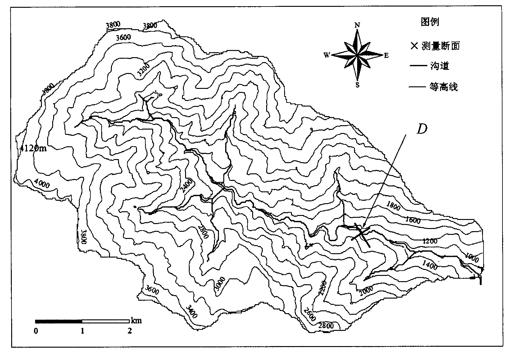
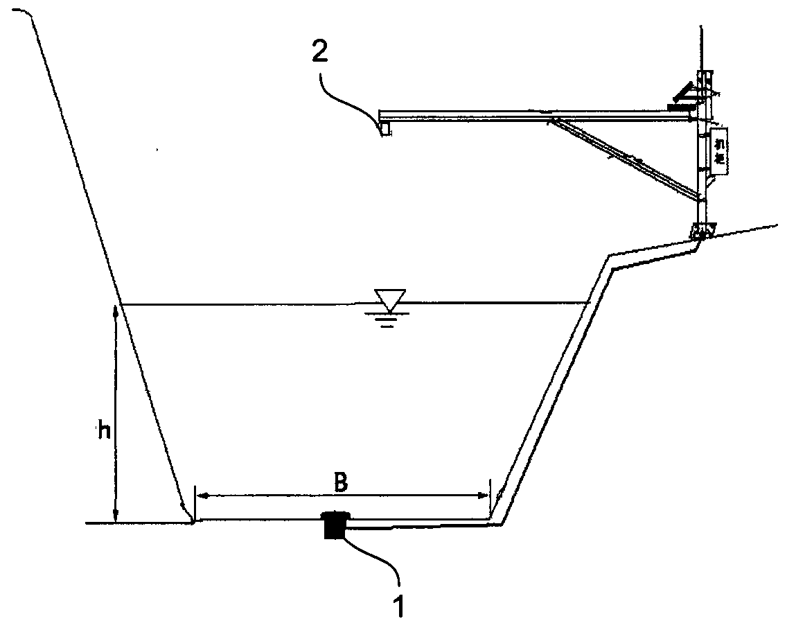
[0100] like Figure 1-1 to Figure 1-6 As shown, a debris flow mechanical parameter monitoring system.
[0101] Step S1, layout monitoring section D
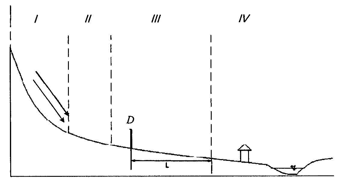
[0102] Picture 1-1 is the elevation map of the debris flow channel; Figure 1-2 It is a schematic diagram of the location of the monitoring section D. In the flow area of the debris flow channel, the monitoring section D is selected at a position where the shape of the channel cross section is regular, the change of channel erosion and silting is small, the channel bed is straight, and the bank slopes on both sides are high and steep.
[0103] Step S2, investigate and determine the background parameters
[0104] On-site investigation to determine the slope I where the monitoring section D is located C =14.1%, monitoring section D width B=30m, debris flow ditch bed roughness n C =0.14, external resistance coefficient m=7.0, maximum safe discharge flow Q of downstream channel p =2400m 3 ·s -1 , the distance L from the mo...
Embodiment 2
[0122] The debris flow early warning system is realized on the basis of the first embodiment of the debris flow mechanical parameter monitoring system. Figure 2-1 It is the flow chart of debris flow early warning data analysis.
[0123] Step S1 to step S4 are implemented according to the content of the first embodiment.
[0124] Step S5, Early warning of debris flow occurrence scale
[0125] Figure 2-2 It is the flow chart of data early warning processing algorithm. The control center calculates the peak flow Q of the debris flow according to formula 9 in real time c , and according to Q c Maximum safe discharge flow Q with the downstream channel p =2400m 3 ·s -1 The scale of debris flow and the level of early warning can be determined based on the discriminant conditions of inter-time flow.
[0126] At time t-1, V C =8.9m·s -1 , γ c =1.95g·cm -1 , h=6m, then at this time, Q c =1602m 3 ·s -1 , as listed in Table 2, the system issues a yellow alert.
[0127] S...
PUM
 Abstract
Description
Claims
Application Information
 - R&D
- Intellectual Property
- Life Sciences
- Materials
- Tech Scout
- Unparalleled Data Quality
- Higher Quality Content
- 60% Fewer Hallucinations
Browse by: Latest US Patents, China's latest patents, Technical Efficacy Thesaurus, Application Domain, Technology Topic, Popular Technical Reports.
© 2025 PatSnap. All rights reserved.Legal|Privacy policy|Modern Slavery Act Transparency Statement|Sitemap|About US| Contact US: help@patsnap.com


